
I’m lost here. I can run a script ok in the control center, but I cannot figure out how to run a script that’s on the Maestro from an arduino. Can I use a Nano or does it have to be an UNO?
I connected gnd to gnd and TX to RX and RX to TX but get nothing.
Hello.
You can use an Arduino Nano. Can you post more information about your setup? In particular, a copy of your Maestro settings file would be very helpful. You can save a copy of your settings file form the “File” drop-down menu of the Maestro Control Center while it is connected.
Also, are you using our Maestro Servo Controller library for Arduino, and what command(s) are you sending from your Arduino code? Could you post a simple Arduino sketch that demonstrates the problem?
Brandon
maestro_settings.txt (4.3 KB)
When I run my own sequence in the Maestro Controller it works.I connect the Maestro RX to the Nano TX and the Maestro RX to the nano TX. (these are pins 0 and 1) I load the script from the Arduino example ‘script’ into the Maestro and then try the script sketch from the Arduino. The gnds of both boards are connected. Nothing happens.
What I want to do is compose 2 or 3 scripts of movement in the Maestro for 3-5 servos and be able to start and stop them with an Arduino.
Just to clarify, pin 1 on the Arduino Nano should be connected to the RX pin on the Maestro, and pin 0 on the Nano should be connected to the TX pin on the Maestro. Can you double check that those are correct?
Also, how do you have everything powered when you try to run the Arduino sketch? Could you post pictures of your setup that show all of your connections?
Brandon
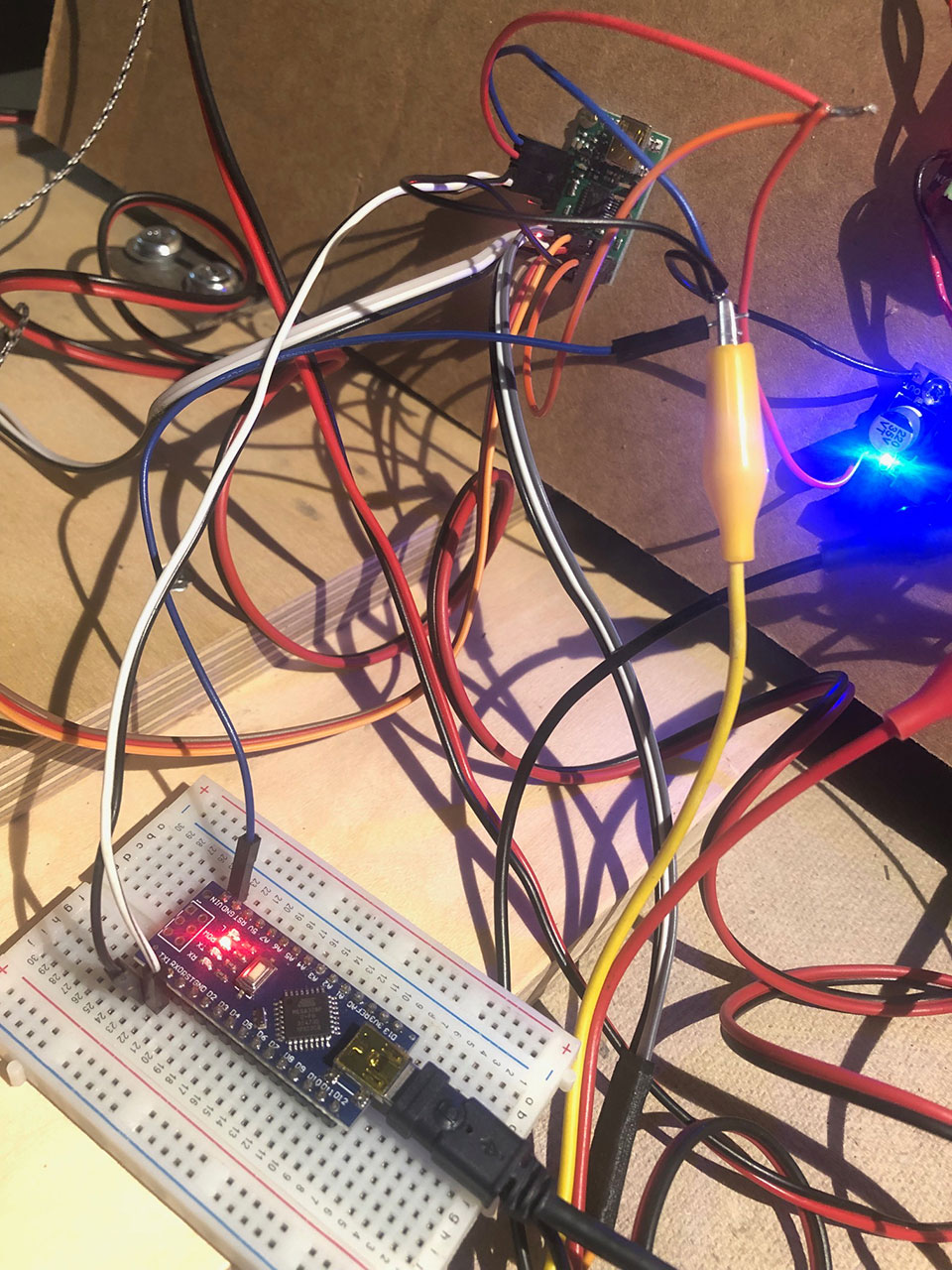
I don’t know if you can make any sense of my wiring pic. Maestro is powered by 5 v reg. Nano is powered by USB. Gnds are connected. Maestro RX (black wire) goes to Nano TX. Maestro TX (white wire) goes to Nano RX. Servos attached to 0, 1, 2. Using Arduino “script” sketch. I copied the script in there to Maestro control. Uploaded script to Nano. Nothing. Am I supposed to send a command thru serial monitor? Maestro control of 3 servos works without Nano.
There is a lot going on with that wiring, including some questionable connections like the alligator clips and twisted wire connections. Also, 5V is the minimum operating voltage for the Maestro, so another potential problem could be that the load from powering the servos is causing the regulator’s voltage to drop and brown-out the Maestro.
Can you simplify the setup by removing everything except the Maestro and Arduino Nano (including your servos), then run your Arduino sketch while the Maestro is powered via USB, so you can monitor the Maestro Control Center and see if the script starts running?
Brandon
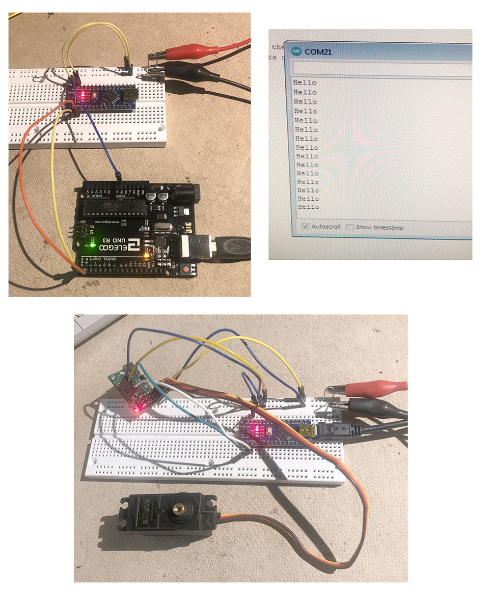
ok. I simplified. I also connected a Nano and an UNO based on a Youtube on serial connecting. I could transmit “Hello” both directions (re-uploading sketches of course) from Nano to UNO, then I tried UNO to Nano. It works.
Then I made a more simplified version of the Maestro and the Nano. I couldn’t get the script sketch to work. The Maestro is powered with 5V from a power supply and the Nano is powered thru USB. One interesting thing is if RX TX was connected between the boards, the sketch wouldn’t compile. It would get stuck before done uploading and I’d have to repower it and disconnect RX TX to upload the sketch. I don’t know if this is an issue or not. Anyways, I still can’t see it run the script on the Maestro.
Thank you for the additional information. Can you try disconnecting the servos and the 5V power from the Maestro and try just powering it through USB as I mentioned in my previous post? The only connections aside from USB that you should need is your two serial wires and a ground wire between the two devices. I noticed the Maestro is indicating an error in your picture, so in this even more simplified setup with it powered via USB, if it is still indicating an error, can you check the “Errors” tab of the Maestro Control Center to see which specific error and performance flags are being indicated?
Brandon
ok, I did what you said, but nothing worked. I was able to get rid of the error light by rebooting the Maestro. I decided to poke around the forum and see if I could find another script or sketch. I was able to get it working with the Arduino sketch below. The RX and TX are on 4 and 5 now. Once I saw it was working I added a servo and 5v power for the servo. I messed with the mapping numbers until I got the full range. It looks like it’s only swinging 90 degrees tho. Ultimately, tho, I want to be able to start and stop scripts on the Maestro with the Arduino. If it’s all on the Arduino, that’s ok too, but I don’t know the commands for that.
#include <SoftwareSerial.h>
#define TXPIN 4
#define RXPIN 5

#define HONRIZONTAL 0

SoftwareSerial maestro(RXPIN, TXPIN);
void setup()// run once, when the sketch starts
{
  // Define the appropriate input/output pins
  pinMode(RXPIN, INPUT);
  pinMode(TXPIN, OUTPUT);
  maestro.begin(9600);
  delay(1000);
}
void loop()
{
  move();
}

void move() {

  settarget(HONRIZONTAL, 0);
  delay(1000);
  settarget(HONRIZONTAL, 180);
  delay(1000);
}

//Send a Set Target command to the Maestro.
//Target is in units of quarter microseconds, so the normal range is 4000 to 8000.
void settarget(unsigned char servo, unsigned int target)
{
  target = map(target, 0, 180, 4084, 24144);
  maestro.write(0xAA); //start byte
  maestro.write(0x0C) ; //device id
  maestro.write(0x04); //command number
  maestro.write(servo); //servo number
  maestro.write(target & 0x7F);
  maestro.write((target >> 7) & 0x7F);
}
Do you know what error was showing before you reset the device (that could be indicative of the problem)? It looks like that code uses software serial instead of hardware serial. Also, that code does not rely on your script since it is controlling the outputs through set target commands, so it’s a good test to see that the serial communication is working. Can you try running the following Arduino code on the same setup that worked with the last code you posted (it should essentially do the same thing, but using our Maestro library)?
#include <PololuMaestro.h>
#include <SoftwareSerial.h>

SoftwareSerial maestroSerial(5, 4);

MicroMaestro maestro(maestroSerial);

void setup()
{
  maestroSerial.begin(9600);
}

void loop()
{
  // Set the target of channel 0 to 1000 us, and wait 1 second.
  maestro.setTarget(0, 4000);
  delay(1000);

  // Set the target of channel 0 to 2000 us, and wait 1 second.
  maestro.setTarget(0, 8000);
  delay(1000);
}
If that works, could you try this Arduino sketch and see if it works with the serial script commands?
#include <PololuMaestro.h>
#include <SoftwareSerial.h>

SoftwareSerial maestroSerial(5, 4);

MicroMaestro maestro(maestroSerial);

void setup()
{
  maestroSerial.begin(9600);
}

void loop()
{
  maestro.restartScript(0);
  delay(4000);
  maestro.stopScript();

  maestro.restartScriptWithParameter(1, 2000);
  delay(4000);
}
As far as the range of the servo, from the settings file you posted earlier, it looks like you actually reduced the usable range from the default of 992-2000 to 1008-1568 in the “Channel Settings” tab, so you’re limiting it to only half of the standard range. Until you get things working and are closer to putting it in your actual setup, I suggest setting the min and max values to their default values for now (min = 992, max=2000). Then, you can increase the range once things are working correctly; however, please note that it is possible to damage some servos by commanding them beyond what they are physically capable of, so when you do that, I recommend following the method described in the second to last question on the “FAQs” tab of the Maestro product pages.
Brandon
Yes, both of these work. I’m still unclear on the difference between hardware serial and software serial. Also the numbers for servo position don’t make sense to me. Like 7000 in the Maestro script is 1500 in the status window.
Also if I reduce the delay in the Arduino sketch it no longer works.
If you remove the status tab, how do you get it back in the control center?
Hello.
-
The Maestro uses units of quarter-microseconds for the set target command, whereas the “Status” tab of the Maestro Control Center shows the target in units of microseconds (which is a more common notation for RC servo pulses). For example, a target value of 4000 will set the pulse width to 1000ms while a target of 6000 corresponds to a pulse width of 1500ms. However, please note that the pulse width range is limited by the settings configured in the “Channel Settings” tab of the Maestro Control Center for each servo, which probably explains why a set target value of 7000 is giving you 1568ms (since your “max” setting is set to 1568 according to the settings file you posted).
-
How much did you reduce the delay? Please note that there are delays in the Maestro’s script as well, so if you reduce the delays in the Arduino sketch too much, it could restart the script before it has time to do anything. If you are still having problems, could you post an updated copy of your settings file as well as your updated Arduino sketch?
-
If you drag one of the tabs out of the Maestro Control Center window, it will create it’s own separate pop-up window. When you close the pop-up window, it will appear in its normal location in the Maestro Control Center window again.
Brandon
My mistake…the 7000 WAS giving a value of 1750 when I went back to the default channel settings. And I see how the delay in the Arduino and the delay in the Maestro can conflict.
With the 992 and 2000, I only get about 90 degrees. I changed it to 496 and 2496 and now I get the full 180 with no straining. Is this normal/ok?
I get a stack overflow/underflow error when I try to connect the Arduino
Most servos can get somewhere between 120-180 degrees of rotation when you expand the pulse width range. As long as your particular servo is not straining or hitting a physical end stop, it should be fine to use it that way.
The stack overflow/underflow error is likely from something in your Maestro sketch. If you can post an updated copy of your Maestro settings file, I would be glad to help you troubleshoot it further.
Brandon
maestro_settings.txt (4.4 KB)
I can’t seem to get it to work with Arduino. Pins are 5, 4…which is RX and which is TX? It worked before. Now I get nothing or an error. The Maestro can run a script on its own.
In the code I posted above, pin 5 is RX on the Arduino and should be connected to the Maestro’s TX pin, and pin 4 is TX on the Arduino and should be connected to the Maestro’s RX pin.
It looks like your script is not set up correctly to be used with the restart script at subroutine command. From the way it is formatted, I suspect you used the “Copy Sequence to Script” button to generate it.
For reference, here is your script:
# Sequence 3

begin
  1000 1984 0 0 0 0 0 frame_0..5 # Frame 0
  1000 9984 frame_0 # Frame 1
repeat

sub frame_0..5
  5 servo
  4 servo
  3 servo
  2 servo
  1 servo
  0 servo
  delay
  return

sub frame_0
  0 servo
  delay
  return
If you command it to start at subroutine 0, it is going to start at your frame_0..5 subroutine and immediately trigger an error since that subroutine needs the values associated with it in your BEGIN/REPEAT loop. The easiest fix for this is probably to put your BEGIN/REPEAT loop in a subroutine. You can do this by adding something like sub Sequence3 before the BEGIN command.
Please note that this will cause the script to continuously loop. If you only want it to run through once, then stop, you can add a QUIT command before the REPEAT.
Brandon
I am completely lost. As soon as I connect the Arduino I get an error. Also copy sequence to script…isn’t that how you get your sequence into the Maestro? How else are you supposed to?
I like the sequencing part of this, but the script part is just too complicated. Maybe I should just use stepper motors…