
First ever post, and I love your products! I’m going to make a fortune with them someday. I’m using your Micro Maestro on a Windows 7 machine in USB chained mode. The Maestro and PC work together as a master controller for up to eight chained Pololu Micro Serial Servo Controllers, each operating an 8-axis robot. In fact, I had the Maestro and one servo controller with one servo each working on the bench just fine (which was a major eureka moment, let me tell you). Hooked the servo controller (supposedly the same way) to a robot with eight servos and it did not work (detail to follow). Put it back on the bench and it still doesn’t work! So unless I destroyed the servo controller somehow, I’m wiring it wrong. What I’m after here is a definitive description of how each should be powered given one excellent Pololu #1642 5VDC 1A wall-adapter power supply (I’ll increase the servo supply to 5VDC and many amps as needed), and how they should be wired for chained serial communications. I’m almost there and will give you what I’ve got.
The Maestro works fine for control of servo 0 using both the Maestro control center application and the Pololu Serial Transmitter application with appropriate bytes. Using short jumpers, I soldered a Pololu #1139 DC Power Adapter barrel jack to the servos’ ground rail (across servos 6 and 7) and onto the + pin of the servo’s power rail. The jack receives the #1642 power supply perfectly, of course. I used a red jumper from my trusty Pololu #1803 Wires with Pre-Crimped Terminals 50-piece Rainbow Assortment F-F between the + pin of the servo power rail and the VIN pin of the Maestro in order to power the Maestro’s logic with the same 5VDC. I hooked a very fine servo purchased from Pololu to the servo 0 pins, and it moves jitter-free on demand.
The serial 8-servo controller is also powered with a single #1642 power supply. A #1139 barrel jack is soldered with short leads to the servos’ ground rail (across servos 6 and 7) and onto the + pin of the servo’s power rail. I hot-glued the barrel jack to the bottom of the circuit board. (I am having second thoughts about attaching the barrel like that; I don’t want to tear the traces off if something puts leverage on the power supply plug when it is inserted therein! But it makes a very neat package.) I shorted the Vcc=Vs jumper in order to power the logic of the 8-servo controller.
The protocol selection jumper is removed from the serial servo controller to use Pololu’s native protocol.
I put a blue (INdigo) #1803 jumper on the logic-level serial INput pin. I put the other end of that jumper on the Maestro’s TX (TTL serial out) pin. The idea is that the Maestro will pass any serial information it receives on the USB to the TTL out pin at the baud rate I set (9600) when I open the Command COM port the Maestro provides my PC. It appears as input on the serial controller’s input pin.
The two wall adapters are plugged into a power strip. When the strip is off, the Maestro is powered by the USB and I see a steady green LED and a double-flashing yellow LED at just over 1-second intervals. When the power strip is on, the Maestro’s LEDs don’t change, though it is now powered by the wall adapter, and the serial servo controller’s yellow LED comes on steadily. This means the serial input line is detected (high), and the servo controller is awaiting serial input.
I use the Pololu Serial Transmitter application to send a nice 5-byte data packet, say, 0x80 1 0 0 0x4F, down the USB line from the PC for the Maestro to pass on to the servo controller. The idea is to set the serial controller’s baud rate. The servo controller is supposed to see serial input, but it DOESN’T! I then send a 3-byte 0xAA 0xC 0x22 command to initialize the Maestro (whose ID is the default 12, or 0xC) and send its servo to the home position (which, as per the Maestro control center application, is NOT in the middle for now so I can use the transmitter application for 3-byte, 5-byte and 6-byte commands one after the other). The Maestro’s servo goes home. I can alternately send a 6-byte packet like 0xAA 0xC 4 0 0x70 0x2E to send the servo to the middle and back to home. The Maestro is working fine. But no matter what I send the servo controller, it doesn’t work. The yellow LED remains steady-- the serial in line is always idle, despite the fact that the Maestro is receiving the data packet (its green LED flickers off an instant) and is presumably passing the unrecognized packet starting with 0x80 on to the TTL output pin at the 9600 baud the transmitter application is set to.
So I consider a common ground, and whether I need one other than the one I hope exists that may be provided by the power strip and the two power adapters. After disconnecting the transmitter application’s COM port and powering down the power strip and pulling out the USB cable, I add a #1803 green for ground jumper between the Maestro’s GND pin next to its VIN pin and the serial servo controller’s GND pin next to its VIN pin. I re-plug the USB cable and see the Maestro’s usual steady green and double-flashing yellow LEDs. I turn on the power strip. No change on the Maestro I can perceive, and the servo controller’s yellow LED goes on and its servo 0 moves a tiny bit. I click ‘Connect’ on the transmitter application, again at a stately 9600 baud. I send a 5-byte data packet, 0x80 1 0 0 0x4F, from the transmitter application. Instantly the servo controller’s red LED starts flashing while the yellow LED shines steadily. Whoa! That LED combination is not described in the manuals. My common ground idea sure didn’t work! But why? And, therefore, what does? I’ve tried a lot of combinations now, common grounds among the Maestro’s servo GND rail and logic GND and the servo controller’s servo GND rail and its logic GND, and every combination therefrom. I’ve reconsidered how I am powering the servo controller AND the Maestro. I can’t see the flaw. I had it working before on the bench, so what am I missing now? When we together get it working, I’ll explicitly detail one working solution for your millions of customers to follow who, like me, will see the brilliance of using the Maestro together with the PC to controll so many servos. Thanks!
Hello,
This is the kind of situation where a picture would be worth a thousand words. Can you post one?
You definitely need to connect the grounds of the two controllers together - any single ground connection should suffice, since all of the grounds on either board are all already connected together. It is unlikely that there is a common ground through your power strip. I do not totally understand the rest of your power setup (e.g. where are Maestro “servos 6 and 7”?), but I assume that it is not an issue since the boards are both running, and you can tell they are not working by the LED states alone.
The undocumented blinking LED pattern of the Mini SSC is just another kind of serial error. It would be interesting to know what happens when you send just a 0x80 - can you try that?
Here is the definitive reference on daisy-chaining. Please make sure that 0x80 is the first byte you are ever sending to the serial chain, so that the Micro SSC can learn the baud rate. You can test the Maestro by itself, with no connections to the Micro SSC, by connecting TX to RX and sending some bytes using the serial transmitter, looking for whether the bytes are echoed back. If you have some other source of serial output, you can also test the Micro SSC by itself. It is possible that the USB dual port mode might be easier to use, and it is definitely worth a try if you are still stuck on this.
-Paul
Thanks for your help, Paul! I’ll take this a step at a time. Here is my Maestro-only setup using a regulated wall-adapter type 5VDC supply (not Pololu’s this time, but it is fine). As you suggested, I used a Pololu jumper between the TX and RX pins so Pololu’s serial transmitter application would echo any byte(s) it transmits:
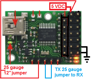
Before transmission I have a green steady LED and a double-flashing yellow LED. I send a single byte, 0xAA. Upon transmission I get a steady red LED and keep the steady green and double-flashing yellow. I do not get any received byte.
I have a second, brand-new Maestro, straight out of the plastic envelope. I used short 25-gauge jumpers and some alligator clips to apply the same 5VDC from the wall adapter’s plug to VIN and GND. I used a 12" 25-gauge jumper between TX and RX. After pulling and reinserting the USB, stopping and restarting the transmitter application and selecting the newly assigned Command COM port, I get a steady green, a flashing yellow on and off equally at about 1 Hz, no red LED, but no echoed message in the transmitter application either. I used the new Maestro and nothing but USB power and the same jumper, in case that is supposed to work. Again, steady green, 1 Hz flashing yellow and no red LED, and no echoed message. If your TX to RX trick works, and of course it should, it isn’t working for me! Weird, is it not? Looking forward to your reply. You’re always very impressive in this forum.
Hello,
The Maestro comes configured for UART mode, so you have to put it into one of the other modes to use its USB-to-serial feature. Can you get it into USB chained mode and try again?
-Paul
Paul, you were absolutely right. When I broke out the new Maestro, I forgot to reconfigure it from its default, UART detect baud rate. I changed it to USB chained, and got my echoed serial transmission as expected. Great job! I then tried the other Maestro which gave me so many weird results, and got the steady red LED, even after I desoldered shared power. I’ve decided I broke that one somehow. I then attempted to make the Mini-SSC work with the new Maestro, and eventually succeeded! It wasn’t perfectly easy, though; there are a series of steps to be made pretty much in order. This is worth passing on, so I’ll be explicit for others after me to find this, as I wish I could have days ago.
I wired the Maestro and the Mini-SSC (8-servo serial controller) like this:
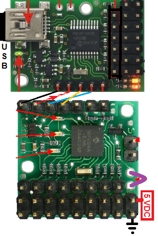
Notice the Mini-SSC shares 5VDC power between the servos and the logic (I used a 1-amp (the bare minimum) wall adapter from Pololu and matching barrel jack soldered to the servo +5 and ground rails). The Vcc=Vs jumper is in place, bypassing the regulator. It also puts the servo power’s +5 volts on the VIN pin. I used a jumper between that pin and the Maestro’s VIN pin to power the Maestro with 5 VDC as well. It worked. Later I took the jumper off to see if the USB would provide enough power to send serial signals to the Mini-SSC, and it did. I wonder if it would for many parallel Mini-SSCs? If not, my jumper from VIN to VIN works . GND is, and must be, common between the Maestro and Mini-SSC(s). TX from the Maestro goes to one or many Mini-SSCs. If there’s ONLY one Mini-SSC, TX from the Mini-SSC may go to RX of the Maestro. When I jumped between my only Mini-SSC’s TX and the Maestro’s RX, I could see my serial transmissions from the PC echoed back in the transmitter application.
I ended up following your recommendation, Paul, and reconfigured the Maestro from USB Chained to USB Dual Port. Everything still passes through the USB and Maestro, but I can just ignore the Maestro and talk to the Mini-SSC on its own port, the TTL Port. I had to look at the Device Manager for the new port numbers; on the earlier Maestro, my computer assigned COM 4 to the Command Port and COM 5 to the TTL Port. On the new Maestro, the Command Port is 8 and the TTL Port is 7. Even the order changed. After changing to Dual Port, I was able to get it all working pretty quickly with the above-pictured wiring. To test my setup, I plugged one servo into channel 0 of the Mini-SSC, and nothing into the Maestro. To avoid seeing that pretty red LED shining bright, I found that a certain sequence of power-up and startup events works best:
- Plug in USB [Maestro: Green LED steady, yellow flash (double)]
- Start Transmitter software application
- Select the TTL Port (see Device Manager)
- Click the Transmitter ‘Connect’ button
- Apply power to the Mini-SSC [Mini-SSC: Yellow steady.]
- Transmit one byte 0x80 (Mini-SSC baud) [Maestro: Green flicker, on after; yellow same flash.] [Mini-SSC: Green flicker, off after; yellow off.]
- Transmit six byte packets of absolute positioning data for servo 0 test:
0x80 0x01 0x04 0x00 0x01 0x7C (Near 500) [Same LEDs]
0x80 0x01 0x04 0x00 0x25 0x7C (Near 5500) [Same LEDs]
So thanks, Paul, you’ve done it again, and I’m up and running! If I ever figure out what killed the first Maestro, I’ll let somebody know. Probably the usual-- cosmic rays, a full moon, and Murphy. And maybe some static electricity…
Hello,
Your description makes sense to me. I am glad that it works for you now!
USB should be able to provide at least 100 mA and probably 500 mA to the Maestro, which would not only be enough to power the Maestro - at 500 mA, it could be the 5V supply for all of the controllers in your chain, if you like, and you could entirely separate the servo supply from the logic supply.
If you want to know why you are getting a red led on the Maestro, you should take a look at the errors tab of the control center. I would be interested to know what you find, since I cannot think of how sending a single 0xAA could possibly cause that. Have you tried resetting the Maestro to its factory settings?
I would be slightly surprised if static electricity killed it. We get a lot of static out here in the winter in Vegas, and while I try to be careful about it, I have received quite a few painful shocks directly through various pins of my Maestros, and I have yet to notice any damage. I am still betting on incorrect configuration or damage from an electrical short.
-Paul