I’ve read that the power connector on the mini maestro 18 is rated at 10 amps, but the trace should be able to handle more than that. I need to connect 12 servos that can each go up to 3amps MAX (per servo, but they should be operating at 1amp each on average), and I read that I could cut a trace in order to separate the power rails. If that is the case, I think it might be better to separate my 12 servos into 2 power rails each connected to the same battery?
If I’m not wrong, I can cut the live wire trace that is under the board between channel 5 and 6, then solder a power source to the board? I suppose that doing so will keep a common GND or do I need to make another connection in order to connect both GND together?
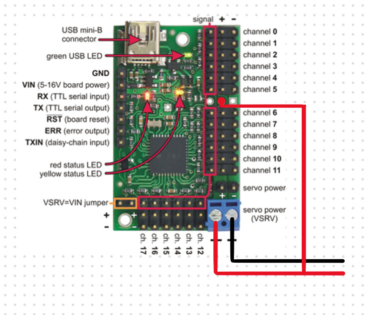
Here’s a schematic of what I plan on doing. If there’s anything I’m doing wrong, could you suggest a better way of doing it?
I moved your post to the “Servo controllers and servos” section of the forum since it is about the Maestro.
The terminal block on the 18-channel Mini Maestro is rated for 10A, but the traces are only rated for 6A. Additionally, the header pins are rated for around 3A. If you are exceeding those limitations, you might consider powering your servos separately from the Maestro board (making sure they still share a common ground with the Maestro).
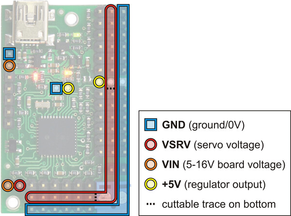
Another potential solution would be to power the servos in banks by cutting the traces on the underside of the Maestro as you mentioned. You can apply power for the channel 0-5 bank using the pin you show in your diagram. The diagram below shows the other 2 locations you can cut the power rail:
You can use the terminal block, or the header just above it, to power the bank of channels 6-11. If you cut both indicated locations, you would need to power channels 12-17 through one of the channel power pins, as there would not be a separate pin connected to that bank.
I think it would be better to have the servos on a separate power rail to avoid breaking the board (since theoretically, if all 12 servos are under load they could reach up to 36 amps)
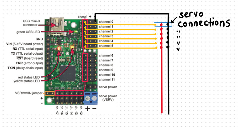
I’m not quite sure how TX and RX signals work but I assume they are independent from the power source. In that case, could you tell me if the following schematic will work with this board? The small blue rectangle represents a servo connector, and I’ll probably extend the same grid using channels 0-11 for all 12 servos.
Yes, the TX and RX signals are separate from the servo power rail. Please note that whatever device you are connecting to TX and RX should also share a common ground with the Maestro.
Your wiring diagram looks good; it should be fine to connect the ground to the servo rail like that.