
Hello,
Can you help me to find the way to correctly connect a Mini Maestro 18-Channel with a Mini Maestro 12-Channel together ? Because i need 27 channel in total.
Thanks you for helping.
Regards,
Hello.
If you are using the Maestro’s serial interface, you can find information about daisy chaining them in the “Daisy Chaining” section of the user’s guide. If you still have any questions after reviewing that information, I would be happy to clarify. Additionally, if you post a proposed wiring diagram or pictures of your connections (before powering up the system), I could look it over for you.
Brandon
Thank you, yes i saw this page but not enough clear for me. I’d like to make a diagram with fritzing to show you if possible but do you know if the components mini maestro exist somewher to upload them in Fritzing ?
Unfortunately, we do not use Fritzing and do not have any resources for it specific to our boards.
The connections should be fairly straight forward, as shown in this picture from the user’s guide:
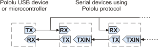
The TX pin of your main controller should connect to the RX pin on each Maestro board, then the TX pin of the second Maestro should connect to the TXIN pin of the first, and the TX pin of the first Maestro should connect back to the RX pin of the main controller. You will also need a common ground connection.
If you are still unsure, even a hand-drawn wiring digram, or a crude one made in a program like Paint, would probably be enough to tell if something were wrong. Also, as I mentioned in my previous post, if you post pictures of your actual setup before you power it on, I would be happy to check it.
Brandon

It looks like you do not have a separate microcontroller (such as an Arduino) pictured in your diagram; could you describe in more detail how you are trying to use those Maestros? Are you trying to control one Maestro from the other?
Brandon
No, il will be connected to an android phone.
I try to do the same thing as this guy ![]() → How To Make A Hexapod Robot. Part 2 of 3: Final assembly and internals. A DIY Robot Project. - YouTube
→ How To Make A Hexapod Robot. Part 2 of 3: Final assembly and internals. A DIY Robot Project. - YouTube
Here is my “almost” complete diagram :
If you can confirm my connections between the 2 mini Maestro would be cool.
And by the way, if you can help to find the good remaining (with “?”) connections would be great ![]()

Thank you for the clarification. The connections between your two Maestro controllers look okay. Please note that to daisy chain Maestro controllers from a USB connection, the first Maestro in the chain (i.e. the one connected to USB) should be configured in either USB Dual Port or USB Chained serial mode; since you are using two Maestro controllers, USB Chained probably makes more sense. The second Maestro (that is receiving the commands through the first) should be configured in UART serial mode. More details about this can be found under the “Using a PC and Maestro together as the master device” heading of the “Daisy Chaining” section of the user’s guide.
It is not entirely clear to me how you want to use the toggle switch, current sensor, voltage sensor, or relay switch. If you can describe how you want them to work, and post details about those other boards (such as links to their product pages or documentation), I could probably help point you in the right direction.
Brandon
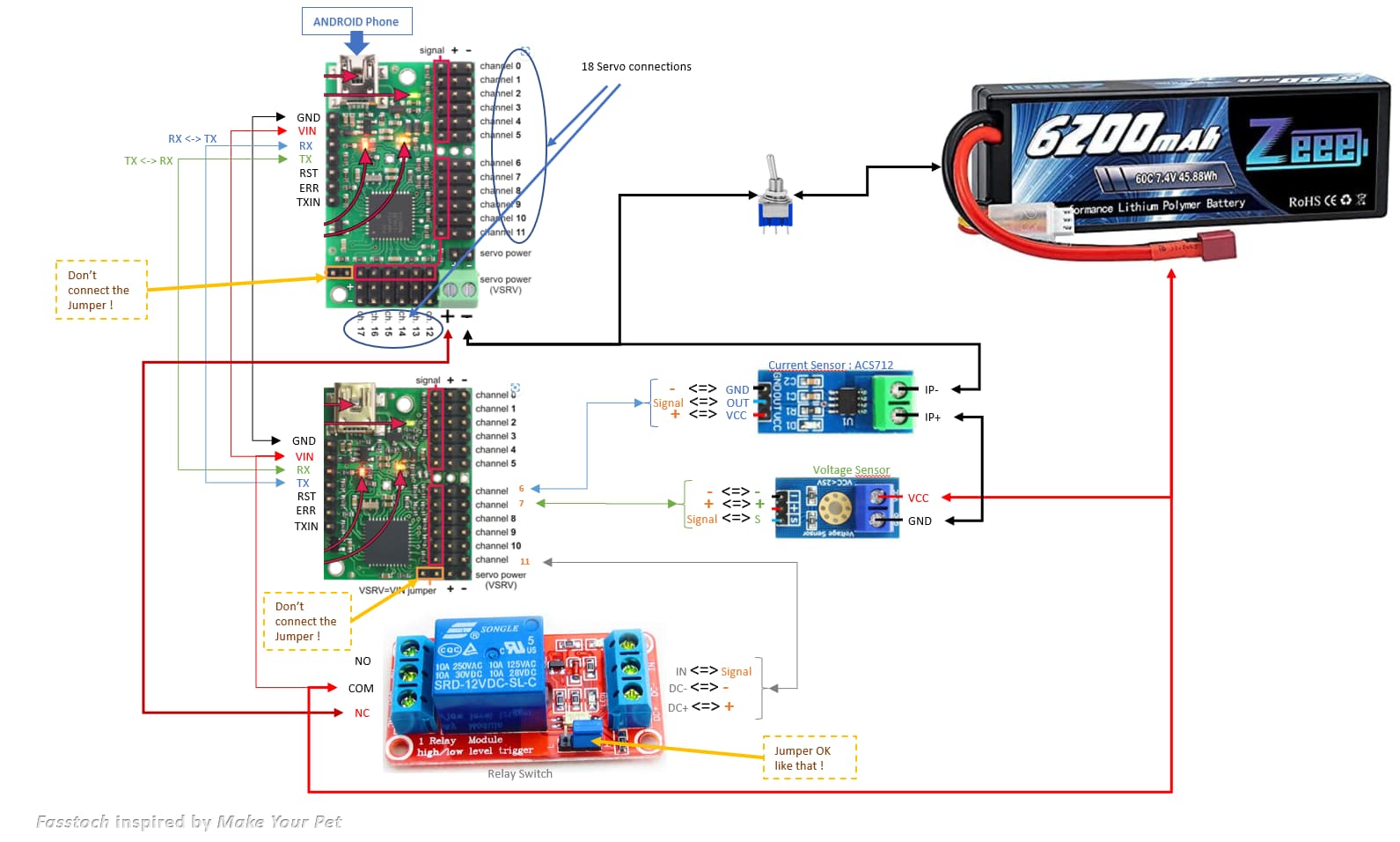
Here is my final diagram …
Does it looks good for you ?
Especially, the jumper on Maestro ? Am i good if i don’t connect them ? (I need 5V, not more, on the Current Sensor)
I cannot say for sure if everything will work how you intend since you have not described what you are trying to do with those extra boards (or supply information about how they work), but I think the general layout mostly looks okay. Here are a couple of things I noticed:
-
It looks like your current sensor is probably wired incorrectly (unless you’re trying to measure the current draw of your voltage sensor). If you want it to measure the current draw of your servos, you would probably need it to be in between your switch and the ground on the servo power rail instead.
-
Your current sensor and voltage sensor should not output more than 5V to the Maestro signal pins; if they output higher than 5V, you might consider using a voltage divider to reduce the maximum voltage down to an appropriate voltage.
-
A 2S LiPo battery can be upwards of 8.4V when fully charged, which might be a little bit high for your servos, so you might double check that your servos can handle that voltage (especially before connecting all 18).
-
It is not clear to me if the + pins on your sensors and relay switch are inputs or outputs. If they are all inputs, then it does not look like you are supplying any external power to the + rail on the 12-channel Maestro, so they will not be powered. If one of them is an output, then you would be powering the other boards from that one. If more than one of them is an output, then you would be shorting them together.
Brandon
thank you for the feedback !
the better description i can do is the link i paste in a previews post. I want to make a Hexapod like the Youtube link and i try to redo the same as the guy shows in the video.
- understood
- Not sure to understand … you mean, in this diagram, the battery wil powering more that 5V, so i need to add a voltage divider between the sensors and the Mastro ?
- understood
- OK, i will analyze that.
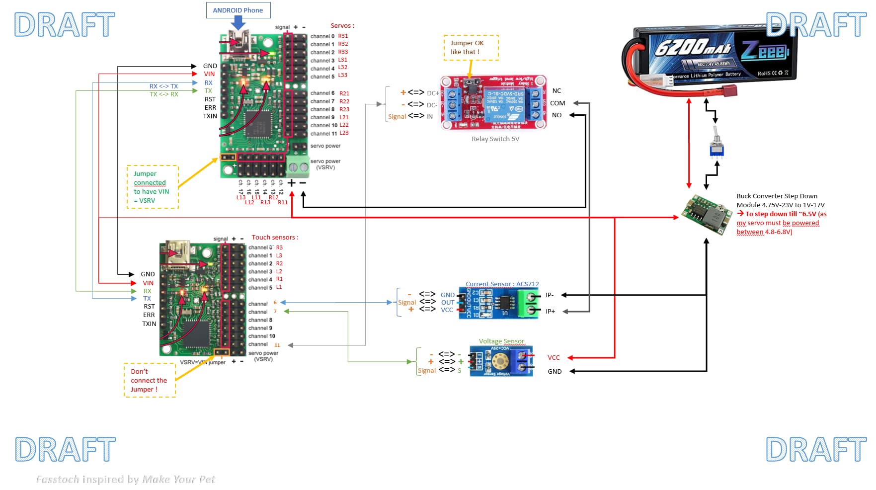
well … i try an update of my diagram :
- updated the Relay Switch (5V) and position
- and i switched the COM / NC to COM / NO for the relay
- Updated the jumpers information → i’m still not sure to understand how to manage the power

→ if i well understood, the battery is powering the main board and if i connect the jumper (on the 18-chanel Maestro), i will have BATT = VIN = VSRV and my board is powered and the servos too (because my servos are limited to 6,8V, that’s why i added a buck converter)
→ the VIN of the second board (12-chanel Maestro) is powering the board but the sensors are powered via the board itself with VSRV to 5V (so i must not connect the jumper → Am i good ?
It sounds like your understanding of powering the Maestro and the VSRV=VIN jumper is correct. Please note however that the 5V regulator on the Maestro (powering the 5V(out) pin) only has about 20mA available for powering other devices, so you should double check that your sensors and relay switch (or anything else you connect to the 12-channel Maestro’s power rail) do not draw more than that.
It still is not clear to me what you want the relay, current sensor, and voltage sensor to do, so I cannot make any meaningful assessment of that part of the diagram. Could you explain what you want them to do? As I mentioned before, a link to their specifications or product pages would also be very helpful.
By the way, it looks like you are planning to power a lot of servos from your step-down regulator. I suspect it will not be able to handle the combined current draw, but that will probably depend on other factors of your system, like how many servos you expect to be powered and loaded at the same time. We generally recommend choosing a regulator that can handle the maximum potential current draw (i.e. the combined stall current of the servos). If your regulator is not powerful enough to do that, you might consider seeing if any of our step-down regulators would be more appropriate.
Brandon
Hi !
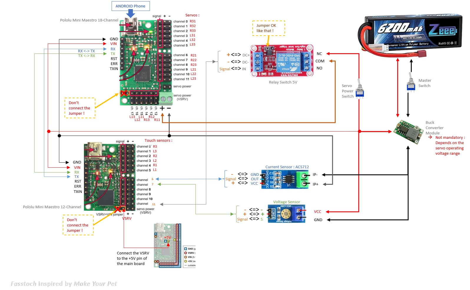
Here is my last diagram should be ok…
The current and voltage sensor will just inform on the android phone that control the robot about their level.
The relay is just to turn of with the controller if necesary.
Yes i will connect 18 servos (the R11,R12 …L22, L23 …) on the first board and touch sensors on the second board
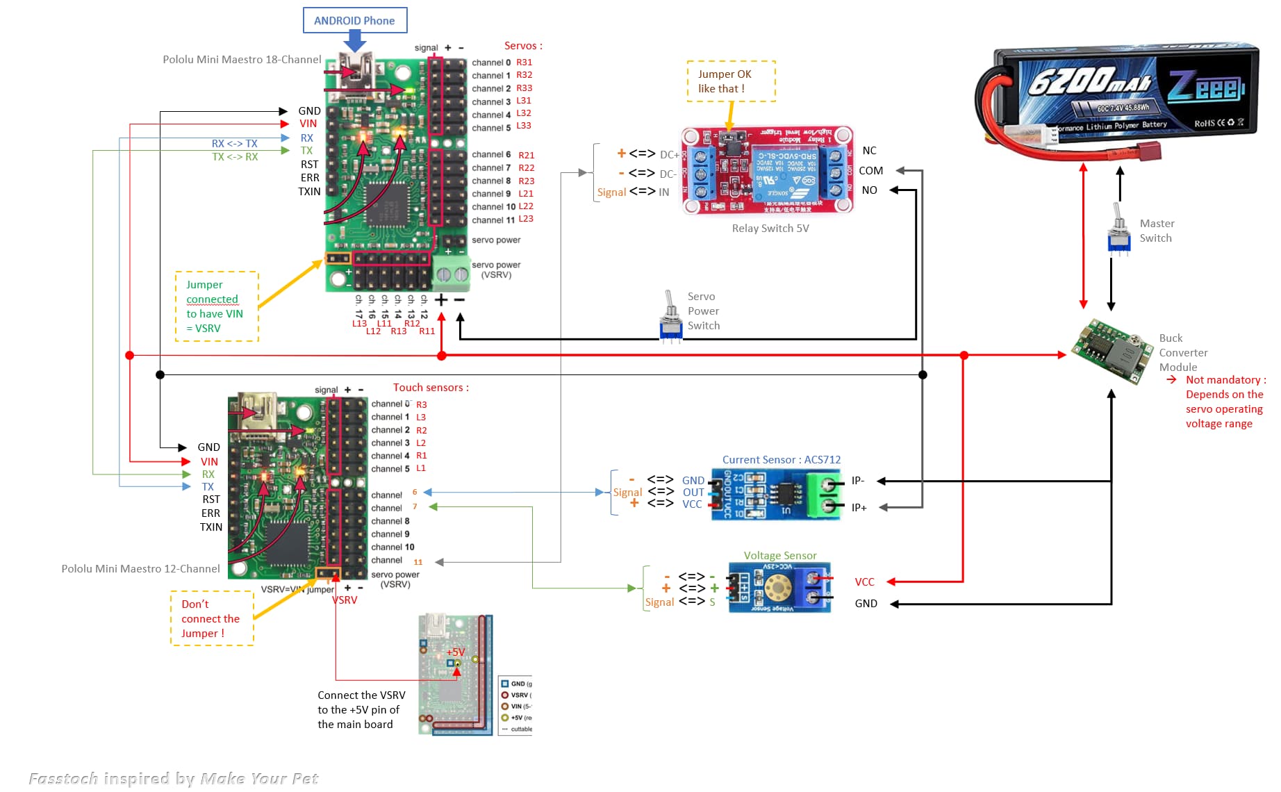
Anything strange for you ?
I understand that you want to read the sensors from your main controller, but it isn’t clear to me what voltage or current you are trying to measure. For example, are you trying to measure the battery voltage or the regulator voltage? Are you trying to measure the current draw of all of your servos, a portion of them, or the entire system? Additionally, since you have not linked to any kind of spec sheet or product page, I cannot say if those other devices are connected properly.
Right now, it looks like your relay is only going to disconnect the ground from the servo power rail of the 18-channel Maestro; however, please note that the board is still grounded through the GND pin next to the VIN pin, so the relay will not disconnect power to the Maestro or servos.
Aside from connections, I suggest you double check all of your power considerations. As I mentioned before, you should make sure your regulator can handle the combined current draw of all of your servos. If you do not know the max current draw of each of your servos, we generally recommend budgeting around 1A per standard servo. Similarly, the 5V pin on the 12-channel Maestro might not be powerful enough to handle your relay, current sensor, voltage sensor, and 6 touch sensors, as it only has around 20mA of current available.
Ultimately, I suggest you start much smaller and built up to a bigger system. For example, start with getting 1 Maestro and 1 servo working from your phone. When you get that working, you can add a couple more servos. If that works as expected, add the second Maestro and 1 sensor, etc.
Brandon
Hi BrandonM !
Sorry, i was out these last days …
Here is the link where i bought the modules (there are no data sheet ![]() but specificatiuons are in the link description :
but specificatiuons are in the link description :
- Battery : Zeee 2s lipo Batterie 6200mAh 7,4V 60C RC Batterie, avec connecteur Deans T Fiche, pour RC Evader BX Auto Car Truck LKW Truggy RC Hobby : Amazon.fr: Jeux et Jouets
- Servos : ANIMOO Servo Numérique Couple élevé 20KG Plein Engrenage métallique Imperméable à l’eau pour RC modèle DIY, Angle de contrôle de 270 ° : Amazon.fr: Jeux et Jouets
- Current and Voltage sensors : WayinTop 2pcs ACS712 30A Module Capteur de Courant Plage Range Current Sensor Module + 2pcs DC0-25V Terminal de capteur testeur de Tension : Amazon.fr: Commerce, Industrie et Science
- Touch sensors : 40pcs Micro Interrupteur de Fin de Course Longue Charnière Levier AC 125V 2A 3 Broches SPDT pour Appareils Ménagers Audio Business Machines Équipement de Communication : Amazon.fr: Bricolage
- Bulk converter : Hailege 10pcs Mini 360 DC to DC Buck Converter Step Down Module 4.75V-23V to 1V-17V : Amazon.fr: Commerce, Industrie et Science
For the questions :
- Yes, i try to measure the current and voltage on the servos.
- Regarding the relay, you mean, that with this connections, it won’t work as expected :(, yes the goal is to diconnect servos if necessary ?
- with the links above, you can help to tell me if all is well powered ?
Again, thank you for your help !
Unfortunately, those Amazon pages do not have very useful information for how those sensors work and how much current they require. Similarly, I didn’t see any information about the current draw of the servos, but they look substantial, so it seems very unlikely that your 3A regulator is going to be able to power them all. Please note that the traces on the Maestro power rail are only rated for 6A, so if your servos are going to draw more than that at any given point, I suggest making the power connections separately from the Maestro board.
As I mentioned in my last post, I highly suggest starting very slowly, with only one or two components at a time and adding more as you go; not only would that help reduce the chance of a catastrophic failure that damages large portions of your system, but if you do encounter a problem, it can help identify the cause of it.
Brandon
Thanks a lot for your help. It helps me to go forward.
Best regards,