Hello,
I am a Mechanical Engineering Student writing Thesis on Vibration Analysis of a Robot in a company.
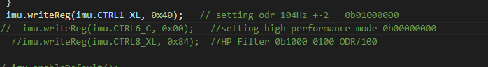
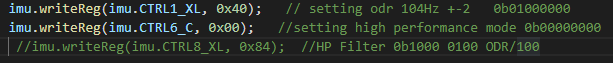
I ordered 3 LSM6DSO to measure the vibration of an Cartesian Robot. The sensor is read by the ESP32 and send it on my computer through Wifi. I first tried with I2C communication with the Code below:
#include <Wire.h>
#include <LSM6.h>
#include <WiFi.h>
const char* ssid = " ";
const char* password = "";
WiFiServer server(8686);
IPAddress local_IP(10, 45, 10, 4);
IPAddress gateway(0, 0, 0, 0);
IPAddress subnet(255, 255, 255, 0);
IPAddress primaryDNS(8, 8, 8, 8);
IPAddress secondaryDNS(8, 8, 4, 4);
unsigned long PreviousTime_acc = 0;
unsigned long AccDelay = 30;
LSM6 imu;
// Calibration values for the accelerometer
const float x_offset = 0.00;
const float y_offset = 0.00;
const float z_offset = 0.00;
// Conversion factor from raw sensor values to g units
const float conversion_factor = 0.061 / 1000.0; //For +-2G
//const float conversion_factor = 0.122 / 1000.0; //For +- 4G : Roboter_acc = 2 m/s/s i.e großer als 2g so 4G ist besser
// const float conversion_factor = 0.488 / 1000.0; // For +-6G
void setup() {
Serial.begin(9600);
if (!WiFi.config(local_IP, gateway, subnet, primaryDNS, secondaryDNS)) {
Serial.println("STA Failed to configure");
}
Serial.print("Connecting to ");
Serial.println(ssid);
WiFi.begin(ssid, password);
while (WiFi.status() != WL_CONNECTED) {
delay(500);
Serial.print(".");
}
Serial.println("");
Serial.println("WiFi connected.");
Serial.print("IP address: ");
Serial.println(WiFi.localIP());
server.begin();
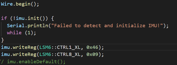
Wire.begin();
if (!imu.init()) {
Serial.println("Failed to detect and initialize IMU!");
while (1)
;
}
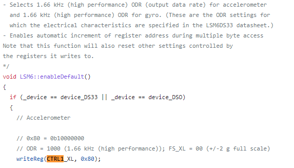
imu.enableDefault();
}
void loop() {
WiFiClient client = server.available();
if (client) {
Serial.println("New client connected!");
while (client.connected()) {
imu.read();
if ((millis() - PreviousTime_acc) >= AccDelay) {
float x = (imu.a.x * conversion_factor) - x_offset;
float y = (imu.a.y * conversion_factor) - y_offset;
float z = (imu.a.z * conversion_factor) - z_offset;
String report = String(millis()) + "," + String(x, 2) + "," + String(y, 2) + "," + String(z, 2) + ";\n";
PreviousTime_acc = millis();
Serial.print(report);
client.print(report);
}
}
Serial.println("Client disconnected!");
client.stop();
}
}
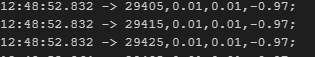
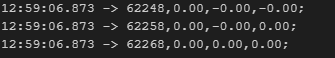
The Problem with I2C communication i am facing is that the data i m getting is not in every 30ms rather in 31ms sometimes. The data as Example looks like this: (millis(Timestamp), x,z, y)
8439 -0.00,-2.00,-0.02;
8469 -0.00,-1.98,-0.00; dt: 30 ms
8500 -0.00,-1.99,-0.01; dt: 31 ms
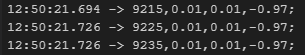
Similarly using SPI, it has better results but when i try to use in 100 hz or to say trigger read data in less than 30 ms, the data is lost in between. (Reading in 10ms)
232851 0.01,0.02,-0.98;
232861 0.01,0.02,-0.98; dt= 10ms
232985 0.03,0.02,-0.98; dt= 125ms
232995 0.03,0.02,-0.98; st = 10 ms
I dont know if the problem is with the type of communication i am using or i should consider other thing. The Datasheet says that it can read upto 6666hz. Thank you.

 .
.