I have the LSM303DLM 3D compass from Pololu. I am using it to keep my dual motor driven robot along a straight line. I used the associated library on Github. The program loads fine but all the outputs are 0. (A:0 0 0, M:0 0 0 or min: { +0, +0, +0} max: { +0, +0, +0}). I tried to run calibrate, heading and serial programs but there is no output at all. (It worked once but since then has given no reading at all)
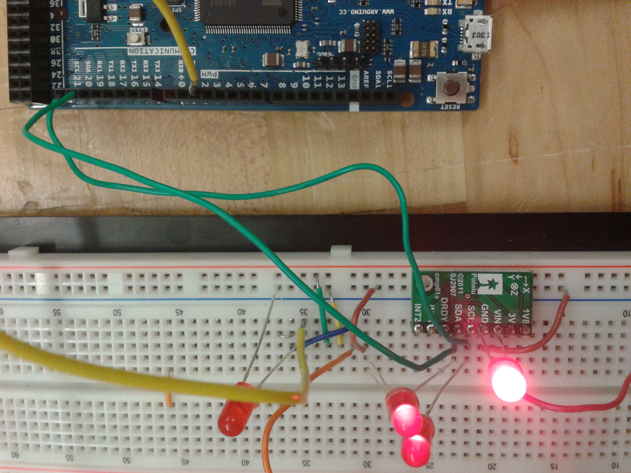
My circuit looks as in the attachment. I am using the compass with Arduino Due. (SDA Com. pin 20, SCL Com. pin 21)
I read earlier discussions on this forum about LSM303 but I can’t figure out why mine is not working.
Please provide some direction to solve the issue.
What do you mean by “it worked once”? What variables did you read out and did the compass produce what appeared to be a continuous set of reasonable values?
I recommend trying your circuit without the LEDs, as the way you have them connected could be causing several problems. It is bad practice to connect an LED directly to a power source (like the one you have between VIN and GND); as with regular diodes, once the voltage across the LED exceeds its forward voltage, the current it draws will increase greatly, and you are likely to burn out the LED or damage your power source this way. The LED could also be causing the VIN voltage to drop too low for the compass to work properly. If you want to connect an LED across VIN and GND, you should use a current-limiting resistor; see this article or this tutorial for more in-depth explanations.
The two LEDs on SCL and SDA might also be causing problems: since SCL and SDA are only pulled high through pull-up resistors, excess current through the LEDs isn’t a problem, but the LEDs are effectively clamping the voltage on those lines to no higher than their forward voltage (about 2 V for red LEDs). That might still register as a logic high in a 3.3 V system, but I would remove them anyway to be safe (they are not likely to show you much useful information anyway).
What are you using to supply VIN? The 3.3 V supply from the Due should be ok, but you should not connect 5 V to VIN since the Due uses 3.3 V logic. Also, do you have a common ground connection between the compass and the Arduino?
Are you using one of the example sketches provided with our library, or did you write your own program? There is a problem with the Due’s Wire library that makes it necessary to specify the device type and address in init() instead of relying on auto-detection; are you doing this? (See the note under the description of init() in the library documentation.)
I made the changes as suggested. I took off the LEDs and specified the SDA, SCL pins on Due in the code. I am using the code given in the LSM303DLH library. I modified it a little for the purposes of my specific program but it is mostly the same. I haven’t had the time to test my code but I run the Calibrate example and it output values other than zero for the magnetometer readings. So that is good.
Also, I am powering the compass using an external 5V power source instead of the Due, since the Due I/Os cannot withstand more than 3.3V continuously. But is that an issue or should I run the compass at 3.3V? (I checked for the output signal voltage to be under 3.3V.)
You should definitely power the LSM303DLM with 3.3 V. You can seriously damage the Due by exposing its inputs to voltages greater than 3.3 V (which you have already done). Unfortunately, attempts to measure the input voltage can be misleading due to the internal diodes on each input to Vcc, which will clamp at about 3.9 V.