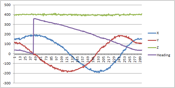
Сalculation Formulas (source):
Heading = arctan(Y/X) for X > 0 and Y >=0
= 180 + arctan (Y/X) for X < 0
= 360 + arctan (Y/X) for X > 0 and Y < 0
Result:
What are you using to communicate with the LSM303DLHC? Could you please post the code you are using and the raw data that you logged to make those graphs?
Do Res[0] through Res[5] contain the values read from registers 03-08 in order? If so, you don’t seem to be combining them correctly. The order of the registers is:
Note that the high byte of each reading comes before the low byte, and Z comes before Y.
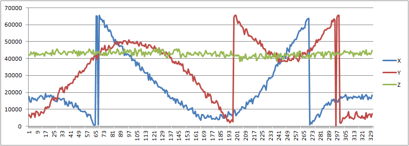
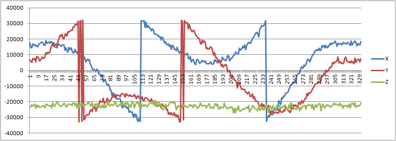
To help me better understand exactly what your code is doing, could you please show me your actual program in its entirety? You can upload it as an attachment or include it in your post and surround it in tags to make it easier to read. I do not have an LSM303DLHC set up to easily allow me to capture data for you, but if you can show me what the data you captured looks like, that would also be helpful. (I am specifically concerned that your graphs seem to show values in the ranges of 0 to 65535 or -32768 to 32767, since the readings from the magnetometer should only fall in the range of -2048 to 2047.)
The graph is exactly what you expect if the bytes are swapped. To check, I wrote a little program to generate the values i={-2048 to 2047}, incrementing by 4, then swapped them and displayed the result as an unsigned int k.
I have similar problem so I decided to write in this thread.
I have Attiny 2313 connected to LSM303DLHC thru I2C. I’ve connected everything and I can read data and pass it to eight digit LCD display. The problem is I’m receiving something like in the first post. The solution presented above (about swapping bytes) is not clear to me, so I’d appreciate any help with my code.
The code I’m using is from documentation - pages 10 and 11. LSM303DLH-compass-app-note.pdf (767 KB)
I’m reading only high x,y,z bytes (because at that level I do not need great precision).
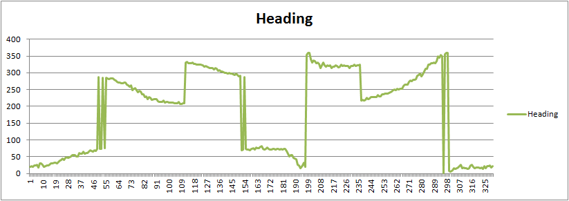
I’ve read the numbers from LCD and drew the chart like below (X had value 0,376,377 so I changed 376 to 276 to show the difference).
I’m concerned that your graph only shows positive values, and I think the problem might be your use of the itoa() function. From this page, it sounds like the third argument is the base (radix) used to display the number; by passing a value of 8, you’re displaying your readings in octal. Furthermore, any base other than 10 causes the number to be interpreted as unsigned. Could you try changing the third argument to 10 in all your itoa() calls so that you display your readings in decimal? You might also consider trying to set up some kind of serial connection so you don’t have to keep reading numbers off the LCD.
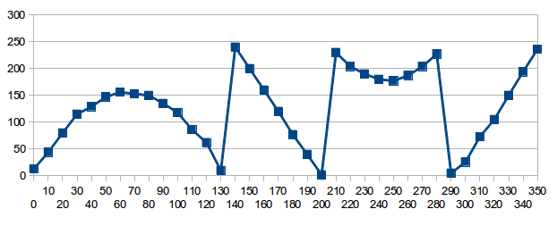
Thanks for help, but something is still wrong in my readings.
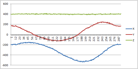
I added 10 as third argument to itoa and now X is constant zero, Y looks like my last chart, and Z is quite contant, but above zero (I’ll ignore it for now). Chart for Y is here:
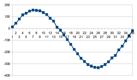
I’ve tried to change Y in libreoffice calc, so it’ll look like sinusoid and I achieved it by substracting 255 and 2*255 from values at certain points (numbers below), but I don’t understand the rule (below there are readings and my corrections), result here:
Additionaly I tried to assign “-10” to my Mx value (Mx = (int) -10), and my LCD shows “-10” so itoa and my LCD can both use negative values, maybe the problem is with casting to int (Mx = (int) MR_Data[0];)?
I noticed another problem with your original code (sorry I didn’t see it earlier). In this section, you are reading 6 registers, starting with MR_REG_M (because you write its register address in the second line):
   i2c_start_wait(KOMPAS+I2C_WRITE);     // set device address and write mode
    i2c_write(MR_REG_M);                        //
    ret = i2c_rep_start(KOMPAS+I2C_READ);       // set device address and read mode
    if ( ret ) {
        lcd_puts("fail");
        _delay_ms(5000);
    }

    MR_Data[0] = i2c_readAck();//read OUT_X_H_M (MSB)
    MR_Data[1] = i2c_readAck(); //read OUT_X_L_M (LSB)
    MR_Data[2] = i2c_readAck();  //read OUT_Y_H_M (MSB)
    MR_Data[3] = i2c_readAck();  //read OUT_Y_L_M (LSB)
    MR_Data[4] = i2c_readAck(); //read OUT_Z_H_M (MSB)
    MR_Data[5] = i2c_readNak(); //read OUT_Z_L_M (LSB)

    i2c_stop();
Additionally, the Z registers in the LSM303DLHC magnetometer come before the Y registers (the order is XH, XL, ZH, ZL, YH, YL, not XH, XL, YH, YL, ZH, ZL, like you would expect). So instead of using OUT_X_H_M, OUT_Y_H_M, and OUT_Z_H_M, you’re actually using MR_REG_M, OUT_X_L_M, and OUT_Z_L_M.
All you should need to do to fix this is to change the argument of i2c_write() in the second line to be the address of OUT_X_H_M (0x03) and then correct the labeling of your plots.