All,
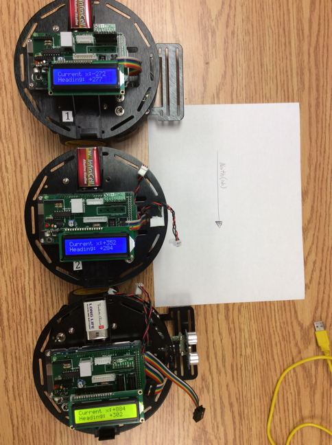
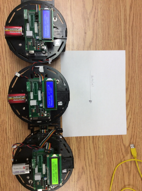
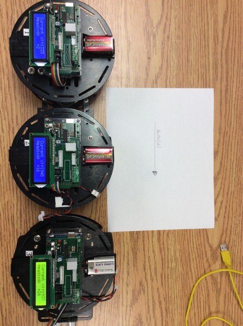
I am using a Pololu LSM303D (Pololu item #: 2127) magnetic compass but have mounted the device upside down. We actually have four of these devices. They all return similar results when I run the ‘heading’ sketch that is provided by Pololu. The heading value fluctuates quickly between very large positive and negative values.
Reading other posts, I see that I can compensate for the upside down mounting in software. I assume that I will have to edit the .cpp file to do this as the heading sketch calls a .heading method. Is there another way to accomplish this?
Will correcting the axis address the varying heading values?
I have used the calibrate sketch to modify the max and min lines in the code:
compass.m_min = (LSM303::vector<int16_t>){-2000, -1300, -2000};
compass.m_max = (LSM303::vector<int16_t>){+1000, +1900, +2400};
My code looks like this:
/* Test the LSM303 compass module
 * Will read the max and min values of the x-coordinate only
 * This will be output on the LCD display
 *
 * Based upon the "Calibrate' sketch that is distributed by Pololu
 * Jun 2017, D. Cope
 *
 */

#include <LiquidCrystal.h>
#include <Wire.h>
#include <LSM303.h>

LSM303 compass;

  /* initialize the LCD with the numbers of the interface pins of the RoboCARP
 * board. These pins are analog being used as digital.
 */
LiquidCrystal lcd(A0,A1,A2,A3,A4,A5);

char report[16];
int dLay = 2000;
float Pi = 3.14159;

void setup() {
  Serial.begin(9600);
  Wire.begin();
  compass.init();
  compass.enableDefault();


  // set up the LCD's number of columns and rows:
  lcd.begin(16, 2);

  /*
  Calibration values; the default values of +/-32767 for each axis
  lead to an assumed magnetometer bias of 0. Use the Calibrate example
  program to determine appropriate values for your particular unit.
  */
  compass.m_min = (LSM303::vector<int16_t>){-2000, -1300, -2000};
  compass.m_max = (LSM303::vector<int16_t>){+1000, +1900, +2400};
}

void loop() {
  compass.read();

  /*

  When given no arguments, the heading() function returns the angular
  difference in the horizontal plane between a default vector and
  north, in degrees.

  The default vector is chosen by the library to point along the
  surface of the PCB, in the direction of the top of the text on the
  silkscreen. This is the +X axis on the Pololu LSM303D carrier and
  the -Y axis on the Pololu LSM303DLHC, LSM303DLM, and LSM303DLH
  carriers.

  To use a different vector as a reference, use the version of heading()
  that takes a vector argument; for example, use

    compass.heading((LSM303::vector<int>){0, 0, 1});

  to use the +Z axis as a reference.
  */

  /*
   * To convert the microTesla readings into a 0-360 degree compass heading,
   * we can use the atan2() function to compute the angle of the vector defined
   * by the Y and X axis readings. The result will be in radians, so we multiply
   * by 180 degrees and divide by Pi to convert that to degrees.
   */

  float heading = compass.heading();


   // Blank the display
  lcd.clear();

  // set the cursor to column 0, line 0
  lcd.setCursor(0, 0);
  snprintf(report, sizeof(report), "Current x:%+d", compass.m.x);
  lcd.print(report);

  // set the cursor to column 0, line 1
  lcd.setCursor(0, 1);
  snprintf(report, sizeof(report), "Heading:%+5d",heading );
  lcd.print(report);

  delay(dLay);
}