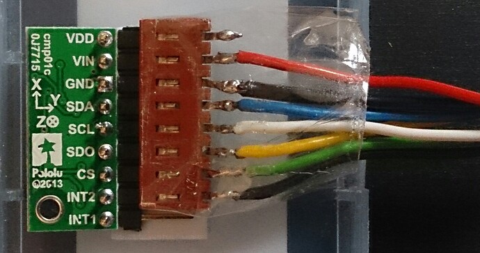
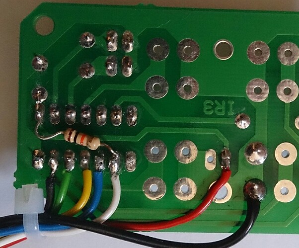
A typical (bad!) output (with the z acceleration axis vertical) is this, where the six readings are Ax,Ay,Az,Mx,My,Mz.
+0032,+0000,+0000,-3193,+0054,+5070
+0032,+0000,+0000,-3196,+0051,+5080
+0032,-0032,+0000,-3196,+0047,+5055
+0000,+0000,+0032,-3163,+0006,+5059
+0000,+0000,+0000,-3209,+0019,+5090
-0032,+0000,+0032,-3144,+0059,+5077
-0032,+0000,-0032,-3179,+0022,+5051
+0000,+0000,-0032,-3172,+0043,+5075
-0032,+0000,+0000,-3170,-0037,+5050
+0032,+0000,+0032,-3209,+0051,+5081
+0032,+0000,+0000,-3191,-0037,+5049
You can see that the magnetometer values look good, whereas all the accelerometer values are wrong - there is no z-axis value, for example.
The I2C is running at 100kHz, and I can send you the I2C driver code if it helps, but I know the I2C is working because I can read back the CTRL registers after loading them.
These are the constants I use in the code:
#define SAD_WRITE	0b00111010	//The slave address ID for high SD0/SDA
#define SAD_READ	0b00111011	//for reading (after a repeated start)

#define CTRL0_ADD	0x9F	//the address of CTRL0 (0x1F) with bit 7 set for auto-increment

#define CTRL0		0b00000000	//for normal mode, filters by-passed
#define CTRL1 		0b01001111	//update after read, and all axes of acceleration enabled at 25Hz
#define CTRL2 		0b11000001	//50Hz anti-alias, +/- 2g, no self-test, (SPI 3-wire)
#define CTRL3 		0b00000000	//No INT1 actions
#define CTRL4 		0b00001000	//accelerometer data ready on INT2.
#define CTRL5		0b00001110	//No temperature, low-res magnetic, 25Hz, latch interrupt on INT2
#define CTRL6 		0b00000000	//+/-2gauss sensitivity.
#define CTRL7		0b00100000	//normal high-pass acceleration filter, no Temp, magnetic always on, continuous conversion mode
//#define STATUS_REG_A 0b00000000	//ditto?

//the first address for six bytes of magnetic data:
#define OUT_X_L_M	0x88	//the address of the low byte of the x magnetic, bit 7 set = autoincrement.
//then 9, A, B, C, D, are the high/low/high/low/high addresses of X, Y, Z magnetic sensors
#define STATUS_M	0x07
#define MASK_ZYXADA 0b00000111

//the first address for six bytes of acceleration data:
#define OUT_X_L_A	0xA8	//bit 7 is set = auto-increment
#define STATUS_A	0x27
#define MASK_ZYXMDA	0b00000111
//__________________________________________________________________
This is the code which reads the accelerometers (written in Hitech C for Microchip 16F1824):
unsigned char read_status_A(void)	{

unsigned char temp;
	send_start();
	write_byte(SAD_WRITE);	//to write to the accelerometer registers.
	write_byte(STATUS_A);	//no repeat
	send_start();				//repeated start for reading
	write_byte(SAD_READ);	//switch device to read from the magnetometer registers.

	temp = read_byte_no_ACK();	//all the bits, no ACK
	send_stop();

	temp &= MASK_ZYXADA;
	return temp;
}
//__________________________________________________________________

void read_accelerometers(void)	{	//sends the three magnetic configuration bytes

	PORTC = 0;//Make sure all the port latches are low before we get going:

	while(INT2 == 0)	{	//check data valid
//	while(read_status_A() == 0)	{	//check data valid
		if(TEST_OUT == 0)
			TEST_OUT = 1;
		else
			TEST_OUT = 0;
		CLRWDT();
	}
	TEST_OUT = 0;

	send_start();
	write_byte(SAD_WRITE);	//to write to the accelerometer registers.
	write_byte(OUT_X_L_A);	//write first byte address to read from (with bit 7 set set to auto-increment).
	send_start();			//repeated start for reading
	write_byte(SAD_READ);	//switch device to read from the accelerometer registers.

	ax[0] = read_byte();	//LSByte
	ax[1] = read_byte();	//MSByte
	ay[0] = read_byte();
	ay[1] = read_byte();
	az[0] = read_byte();
	az[1] = read_byte_no_ACK();
	send_stop();

	x_acc = ax[1];
	x_acc <<= 8;
	x_acc |= ax[0];
//	x_acc >>= 4;	//acceleration values are sent left-shifted!
	x_acc_value = (double)x_acc;

	y_acc = ay[1];
	y_acc <<= 8;
	y_acc |= ay[0];
//	y_acc >>= 4;	//acceleration values are sent left-shifted!
	y_acc_value = (double)y_acc;

	z_acc = az[1];
	z_acc <<= 8;
	z_acc |= az[0];
//	z_acc >>= 4;	//acceleration values are sent left-shifted!
	z_acc_value = (double)z_acc;
}
//__________________________________________________________________


