Hello,
I am having some trouble with my LSM303DLH. I calibrated, i can read heading and all is well, but:
I do something like:
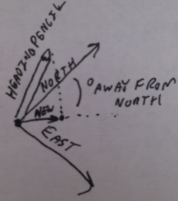
currentHeading = compass.heading((LSM303::vector){0,-1,0});
I understand {0,-1,0} is the orientiation vector, so we can put the board in arbitary orientation.
I noticed:
{0,-1,0} - {0,-1,-1} and {0,-1,1}
gives nearly the same results in my configuration. my sensor is mounted 90degree sideways.
Could someone explain the {0,-1,0} part? My vector math is not good, so i am having some trouble. by trial and error, I found that 0 does not do anything, and this thing can be in 3^3 states total.
the problem I am having is when the bot is stationary, all is fine. but if we are turning to a heading, once in a while I get errorful values.
For example:
h180 <- command to turn to 180 deg
0 3 1 359 3 <- last 5 readings
3 177 180 clock 65 (current heading, angular dist, target heading, turnng clock or counterclock wise, motor power)
3 1 359 3 344
344 -164 180 counter 61
1 359 3 344 28
28 152 180 clock 58
359 3 344 28 352
352 -172 180 counter 63
when the robot turns from 0 to 90 or 90 to 180 the code works perfect. when the bot turns 180d sharp, the first few readings jitter in sign, and this makes the robot jitter when turning. it always turns to correct heading, but when it does sharp turns, it jitters.
Any ideas recomendations greatly appreciated.
Best.