I purchased one of the boards and connected it to my controller, the goal is to use it in an automated boat so as to get headding directions and drive the boat in the direction of the next GPS marker.
At present I am gettign data from the board so the arduino is having no problems talking to the unit but when I use the recomended calibration technique and code I am getting a response of x_min = -4096 throwing the whole thing well out of wack.
So by carefully alligning it to the point just before this i take the best number before the jump and use that.
BUT north is no where near where it should be, I have a cuple of other manual compasses that I am using to varify the direction but it seems that the unit is a good 40degrees off.
Am i doing something wrong?
The acid test will be when this thing gets in the water as we know that it is going to be hammerd by the surf and am really looking forward to pulling some of the telemitry data from it
In the event the ADC reading overflows or underflows for the given channel, or if there is a
math overflow during the bias measurement, this data register will contain the value -4096 in
2’s complement form. This register value clears after the next valid measurement is made.
The magnetic readings you are getting are probably sometimes larger than the max it can handle at the current gain setting. Try reducing the gain.
Do I do this from the atmega’s setup routine or do i have to do this from the lib?
The compases i am using are pointing to magnetic north and are not compensated, I was assuming that the magnetometer would be pulling its direction from magnetic north also?
This is also the first time I have used the i2c bus, am I correct in thinking that you can use the same bus for multiple devices and all you need to do is poll them using their address?
That code should work! You would put that in the Arduino’s setup method right after compass.enable().
Yes, that’s how I2C is meant to work. There are some implementation details, of course, like you want to ensure that all of your I2C devices can operate at the bus voltage (5V in your case), and that your addressing scheme doesn’t conflict. For example, you can’t change the address of the compass, which potentially could be bad if some other device needed to use that address.
Section 9.2.1 refers to CRA_REG_M (00h) and waffles on about how the 8 bits are set.
Section 9.2.2 refers to CRB_REG_M (01h) and has a table in it table 60 and 61 that are refered to as CRA_REG and explains what the 8 bits are for…
So is the gain setting set using CRB_REG_M or CRA_REG.
I did test that cone and it made things worse however it also did not seem to limit the resolution to what is in the table as I expected so im guessing im missing something.
I had to cardcode the hex for CRB_REG_M as it was not seen in the defines.
Yea, that datasheet is a mess. Basically the only thing you can trust is contents of table 60; column 1 in table 61 is just wrong, and names of both tables 60 and 61 are wrong. Despite that, I still think you had the right code. The gain setting is definitely CRB_REG_M at address 0x01. Since the library’s defines are in the library’s .CPP file they are inaccessible to your sketch. I would recommend just copying the defines that you need into your sketch. How did it make things worse? What did the serial monitor output look like before and after you made the gain configuration change?
This shows it is working, one word of warning however is that when I first set it up it was not and there seemed to be little change until after a reboot of the unit (full power cycle) so i suspect at some stage i sent somethign to it that is did not like.
I chose the 1.9 range and when compared to the compasses the digital unit is showing me north is actually at 340 degrees on the other compass. or 40 degrees west i hink the term would be.Down here in NZ true north is 20 Degrees East so that cant be the problem.
EDIT:
And altering the resolution did not fix this. all the resolutions have the same resuls so either my compasses are wrong or i have set something up incorrectly in the software.
Well it seems to be working well and keeps the headding right up until the unit is tilted 45 degrees upward and seems to handle some prety impressive rocking
Now for the hard part, as this unit is going to be in the water its likley never to be sitting on the actual direction and will sway from one side to the other so i need to somehow average the readings but like many others you cant average a number that wraps.
for instance my target headding is 20 degrees and i take 20 samples that end up being
20, 5, 358, 18, 30, 42, 90, 50, 22, 19, 2, 340, 336, 355, 0, 17, 8, 351, 12, 21
The numbers are stored in an array and doing an average on them gives me 104.8 degrees. ANy sugestions as to how I could handle this?
Did you figure out a solution to the heading offset issue? Can you correct it by simply adding a constant angle offset to the heading reported by the compass?
To average readings that cross the 360-0 transition, you could keep track of the averages of the x, y, and z vectors (or just sum them) and calculate a single heading based on those, instead of trying to average the heading directly.
You could also keep track of the differences between your target and measured headings by subtracting the target heading from the measured heading, then adding or subtracting 360 to ensure it is within the range of -180 to +179. Averaging these would tell you how far off you are from the target heading.
Maybe you just mistyped this, but 340 degrees is 20 degrees west. Also, according to this page it looks like true north is 20 degrees west of magnetic north in NZ. I don’t understand exactly what you tested, but are you sure that it is not somehow working perfectly?
Kevin: I have not found a solution for the headding as yet. I am not sure if this is normal or if i have done somthign wrong.
What I am trying to prevent is the boat firing its motors and triving the unit in circles tryign to locate N as with a GPS unit the direction is only reliable after about 6 knots and our top speed on this unit is likley to only be about 2 knots. So i want to take a bearing and try and head in that direction as best as possible with a devition of a few degrees either side.
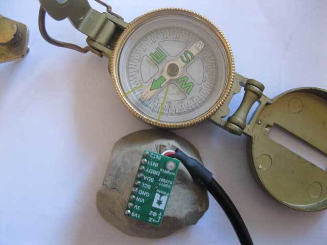
Paul: The actual compass is pointing toward North, then I allign the output of the LSM303 so the compass output is 0 it is pointing toward 320degrees on the actual compass and not north as I would have expected.
So as to explain things a little better here is a photo, keep in mind that bringing the two closer caused the north to be drawn closer to the LSM303 but when they are appart N is where it should be and the LSM is outputing a prety constand flow of 0’s
OK, well now I am embaresed. Yes it appears that the unit is reading true north and not magnetic north…
Now for the bad news, well good actually. I left the compass where it was in the photo and moved the LSM303, now my test bench for this is a formica bench made from wood. it turns out that there is somethign metal in as when i move the compass to different locations the needle no longer points to where it should. So that explains the strange readings and why things dont line up when its on the bench.
When its not on the bench the reading just happens to be around 21 ish degrees out and that is as paul stated what it should be from Magnetic North down here in NZ
Now to deal with the deviation and to smooth the headding.
Ah, the metal in the table explains a lot! The environment of a compass can have a large affect on its performance. To get the best performance, you want to calibrate the compass while it is installed where you are going to use it.
The LSM303 is reading true north and the normal compass is not.
Once the unit is in place I will have to calibrate it in the water as the this thing will be a little too big and heavy to throw around the room I am contemplating putting both the GPA and Compass on a mast above the hull so as to try and keep it away from the motors also I may have to power cycle the motors when taking readings so as to drop the EMF.
I will try and sheild as much as possible with aluminium foil and mesh.
The LSM303DLH does not correct for magnetic declination automatically (doing so would require location and a map of the world’s magnetic declination, which changes over time); the LSM303DLH will be trying to indicate Magnetic North.
Darn, then something is still way off. there is definatly a differnce form the reading im getting on the LSM303 and the compass. its about 20 degrees
so when the compass is pointing to magnetic north the LSM303 is pointing 20 degrees west.
It might be that you need to do more sophisticated calibration to get better than 20 degrees - here is a PDF describing a much more precise (and difficult) method. In your case, it might be good enough to just subtract 20 degrees from the reading. Have you tried it pointing South, East, and West? How resistant is it to tilting up and down? (That is the main point of using a tilt-compensated compass, after all.)
Also, the way you are describing the results of your tests continues to be very confusing, which makes me worried that you do not have a clear idea of what you are actually doing. For example, you just said “…when the compass is pointing to magnetic north…” - but does your compass ever do anything else??


 however it also did not seem to limit the resolution to what is in the table as I expected so im guessing im missing something.