Hello all,
I have been spending A LOT of time trying to get this tilt adjusted compass going, i have been changing over RyanTM’s code so it can compile on MikroC.
I have got the magnetometer working what seems to be 100%, it generally gives a heading ±2 degrees. I have also implemented all of the maths for the tilt adjustment and checked all the calcs in spreasheet.
But where i am having issues is with the accelerometer. It reads the registers but the data doesnt seem to make sense to me.
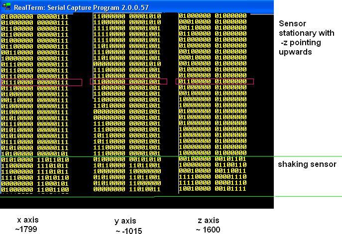
Attached is the image of the raw data outputted every 1 second through serial.
I would of expected the output to be around 0 for 2 axis and ± 1g for the other direction.
I have CTRL_REG1_A set to 27 currently.
I have tried adjusting CTRL_REG4_A aswell to ±8g, and tried averaging 20 times over 1 second to see if it changed much but with no luck.
Below is my reading in code.
void I2C_read_Accelerometer(void)
{

 I2C_Start();            delay_ms(1); //send START
     I2C_Wr(0x30);           delay_ms(2); //Write device address to bus for Write mode  ACCEL_ADDR from Arduino ex
     I2C_Wr(0x28);           delay_ms(2); //Write desired address bits                  x axis MSB
     I2C_Repeated_start();   delay_ms(1); //send repeated start
     I2C_Wr(0x31);           delay_ms(2); //Write device address to bus for Read mode   taken from MikroC I2C example
     ACC_data[0]=I2C1_Rd(0);  delay_ms(1); //Read in data from register
 //    ACC_data[1]=I2C1_Rd(0);  delay_ms(1); //Read in data from register
 //    ACC_data[2]=I2C1_Rd(0);  delay_ms(1); //Read in data from register
 //    ACC_data[3]=I2C1_Rd(0);  delay_ms(1); //Read in data from register
 //    ACC_data[4]=I2C1_Rd(0);  delay_ms(1); //Read in data from register
 //    ACC_data[5]=I2C1_Rd(0);  delay_ms(1); //Read in data from register
     I2C_Stop();             delay_ms(5); //send STOP

     I2C_Start();            delay_ms(1); //send START
     I2C_Wr(0x30);           delay_ms(2); //Write device address to bus for Write mode
     I2C_Wr(0x29);           delay_ms(2); //Write desired address bits                  x axis LSB
     I2C_Repeated_start();   delay_ms(1); //send repeated start
     I2C_Wr(0x31);           delay_ms(2); //Write device address to bus for Read mode
     ACC_data[1]=I2C1_Rd(0);  delay_ms(1); //Read in data from register
     I2C_Stop();             delay_ms(5); //send STOP

     I2C_Start();            delay_ms(1); //send START
     I2C_Wr(0x30);           delay_ms(2); //Write device address to bus for Write mode
     I2C_Wr(0x2A);           delay_ms(2); //Write desired address bits                  y axis MSB
     I2C_Repeated_start();   delay_ms(1); //send repeated start
     I2C_Wr(0x31);           delay_ms(2); //Write device address to bus for Read mode
     ACC_data[2]=I2C1_Rd(0);  delay_ms(1); //Read in data from register
     I2C_Stop();             delay_ms(5); //send STOP

     I2C_Start();            delay_ms(1); //send START
     I2C_Wr(0x30);           delay_ms(2); //Write device address to bus for Write mode
     I2C_Wr(0x2B);           delay_ms(2); //Write desired address bits                  y axis LSB
     I2C_Repeated_start();   delay_ms(1); //send repeated start
     I2C_Wr(0x31);           delay_ms(2); //Write device address to bus for Read mode
     ACC_data[3]=I2C1_Rd(0);  delay_ms(1); //Read in data from register
     I2C_Stop();             delay_ms(5); //send STOP

     I2C_Start();            delay_ms(1); //send START
     I2C_Wr(0x30);           delay_ms(2); //Write device address to bus for Write mode
     I2C_Wr(0x2C);           delay_ms(2); //Write desired address bits                  z axis MSB
     I2C_Repeated_start();   delay_ms(1); //send repeated start
     I2C_Wr(0x31);           delay_ms(2); //Write device address to bus for Read mode
     ACC_data[4]=I2C1_Rd(0);  delay_ms(1); //Read in data from register
     I2C_Stop();             delay_ms(5); //send STOP

     I2C_Start();            delay_ms(1); //send START
     I2C_Wr(0x30);           delay_ms(2); //Write device address to bus for Write mode
     I2C_Wr(0x2D);           delay_ms(2); //Write desired address bits                  z axis LSB
     I2C_Repeated_start();   delay_ms(1); //send repeated start
     I2C_Wr(0x31);           delay_ms(2); //Write device address to bus for Read mode
     ACC_data[5]=I2C1_Rd(0);  delay_ms(1); //Read in data from register
     I2C_Stop();             delay_ms(5); //send STOP

//   early debug
     testa=ACC_data[0];
     testb=ACC_data[1];
	   setTX();
           Usart_Write(testa);
           delay_ms(1);
           Usart_Write(testb);
           delay_ms(1);
            setRX();


     Ax_raw = (int)(((ACC_Data[0] << 8) + ACC_Data[1])>>4);
     if (Ax_raw > 2047) {Ax_raw = ((Ax_raw-2048)+1)*-1;}

    Ay_raw = (int)(((ACC_Data[2] << 8) + ACC_Data[3])>>4);
     if (Ay_raw > 2047) {Ay_raw = ((Ay_raw-2048)+1)*-1;}

     Az_raw = (int)(((ACC_Data[4] << 8) + ACC_Data[5])>>4);
     if (Az_raw > 2047) {Az_raw = ((Az_raw-2048)+1)*-1;}


  }
I was hoping someone might be able to offer some insight.
Thankyou