For what now appears to be no real reason (well, perhaps based on some comment I found somewhere on the net and/or misreading the data sheet), I expected the LSM303DLM acceleration values to be directly in mg (i.e. 10e-3 x g).
Observations of an LSM303DLM (Pololu #1273) suggest the values are simply scaled in the sensor to fit the 16-bit range, that is “full scale” == +/- 2^15, where the actual value of full scale depends on the FS bits (+/- 2g, 4g or 8g).
i.e. to convert to an acceleration measure a.x to g’s, use:
gx = (float)a.x / FS_Gwhere:
FS  Range   Divisor (FS_G)
00  2       2^14
01  4       2^13
11  8       2^12
e.g., for FS = 00
gx = (float)a.x / (1<<14)Ok, kind of obvious in hindsight.
The datasheet does note a procedure in section 4.1 to determine the sensitivity “calibration” by measuring the maxima on rotating about each axis and assuming g to be 1.0; I wish they could have simply said “scale by 2^14 (FS=00), 2^13 (FS=01) or 2^12 (FS=11)”.
Ben
Below are my notes on this, if anyone’s interested.
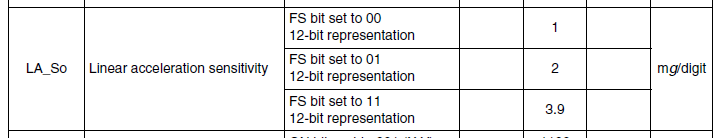
The data sheet Sensor Characteristics lists LA_So ‘Linear acceleration sensitivity’ as a “12-bit representation”, which I initially interpreted to mean a range of 12 bits, or -2048 to 2047 - however it means simply that the range is 12 bits; the least 4 bits of the 16 bit value are meaningless (zero, it seems).
It notes the sensitivities for each range as:
FS      range  sensitivity, mg/digit
00        2       1
01        4       2
10        8       3.9
With the FS bits of CTRL_REG4_A set to 00 (the default) which the data sheet says is a full scale range of +/-2G, and the chip (board) mounted with Z up, I’d presumed raw measurements from the accelerometer of around (0,0,1000).
Here’s what I actually get (code is at the end):
(fields are acceleration x, y, z followed by magnetometer x, y, z)
Init FS 00
+0000 +0000 +0000	-0168 -0263 +0590
+2320 -1552 +14496	-0169 -0262 +0591
+1440 -0320 +16176	-0167 -0262 +0592
+1504 -0464 +16272	-0164 -0264 +0591
+1552 -0464 +16080	-0167 -0264 +0588
+1408 -0656 +16016	-0167 -0262 +0590
+1408 -0304 +16080	-0164 -0266 +0594
+1280 -0672 +16160	-0164 -0267 +0592
+1600 -0656 +16192	-0167 -0260 +0587
+1312 -0432 +16256	-0164 -0263 +0590
+1488 -0688 +16016	-0165 -0267 +0590
+1456 -0560 +16288	-0167 -0262 +0588
on rotating the board, the X and Y values increase depending on the rotation axis, Z decreases, as expected. Magnitudes are about the same as above.
Vigorously shaking the board gives peaks of around 32000 (i.e. max signed int):
+1344 -0688 +16192	-0153 -0268 +0589
+1808 -0496 +16480	-0154 -0268 +0592
+1376 -0464 +16528	-0152 -0267 +0592
+6416 -4816 +24320	-0122 -0292 +0588
-0320 -2752 +15936	-0151 -0248 +0629
+21072 -1536 +32752	-0235 -0275 +0640
-0848 +0064 -8464	-0193 -0255 +0634
-1344 -2192 +16448	-0202 -0276 +0620
+0784 +0960 +16720	-0164 -0263 +0612
+3776 -1296 +15552	-0085 -0292 +0578
+22960 -5920 +32752	-0116 -0289 +0589
-9808 +3136 -32704	-0167 -0288 +0616
FS = 10 (+/-4g)
Init FS 10
+0688 -0736 +15008	-0148 -0255 +0565
+0784 -0240 +8128	-0150 -0257 +0571
+0672 -0256 +7888	-0145 -0255 +0567
+0816 -0368 +8032	-0149 -0258 +0571
+0656 -0272 +8032	-0147 -0251 +0567
+0736 -0480 +7872	-0147 -0253 +0567
+0688 -0352 +7984	-0148 -0254 +0567
+0800 -0272 +7888	-0149 -0255 +0568
+0912 -0352 +7888	-0148 -0256 +0570
+0656 -0448 +7984	-0144 -0257 +0569
shaking:
+8144 -3584 +10400	-0047 -0295 +0588
-3952 -1136 -13552	-0047 -0282 +0589
+2224 -0400 +7280	-0038 -0282 +0577
+4144 -0720 +8592	-0050 -0278 +0578
-11712 +2704 -0208	-0039 -0265 +0612
-27728 +0576 +2832	-0045 -0305 +0584
+18640 -1840 +20704	-0088 -0277 +0639
+1840 +0608 +8560	-0026 -0214 +0597
+0704 -1888 +5344	-0117 -0251 +0580
+0576 -0336 +7792	-0157 -0262 +0590
+0768 -0208 +7952	-0155 -0260 +0589
+0736 -0400 +8112	-0155 -0259 +0588
FS = 11 (+/- 8g)
Init FS 30
+0000 +0000 +0000	-0156 -0256 +0587
+0240 -0192 +4144	-0156 -0256 +0587
+0400 -0144 +3968	-0156 -0256 +0587
+0448 -0208 +3936	-0156 -0256 +0587
+0352 -0080 +3920	-0156 -0256 +0587
+0416 -0288 +4048	-0156 -0256 +0587
+0320 -0208 +4032	-0156 -0256 +0587
+0576 -0176 +4032	-0156 -0256 +0587
+0416 -0208 +3856	-0156 -0256 +0587
+0384 -0176 +3968	-0156 -0256 +0587
+0272 -0192 +3968	-0156 -0256 +0587
+0288 -0304 +3936	-0156 -0256 +0587
+0352 -0160 +3968	-0156 -0256 +0587
+0384 -0192 +3920	-0156 -0256 +0587
+0224 -0336 +3936	-0156 -0256 +0587
+0432 -0288 +3888	-0156 -0256 +0587
+0384 -0304 +4032	-0156 -0256 +0587
shaking:
+0096 +4080 -0144	-0156 -0256 +0587
+1008 +2304 +3424	-0156 -0256 +0587
-1008 -0016 -7184	-0156 -0256 +0587
+2224 -0720 +17296	-0156 -0256 +0587
+3456 +2144 +7104	-0156 -0256 +0587
-1104 +1792 -7232	-0156 -0256 +0587
+4832 -0352 +1520	-0156 -0256 +0587
+4688 -0672 +14416	-0156 -0256 +0587
+0848 -0224 +3824	-0156 -0256 +0587
/*
 * minimal? test of LSM303
 */

#include <avr/io.h>
#include <pololu/orangutan.h>
#include <math.h>
#include <stdlib.h>
#include <string.h>

#include <stdlib.h>
#include <string.h>
#include <stdio.h>

typedef struct vector
{
  int16_t x, y, z;
} vector;


/*
acceleration sensor ranges and scale
- same for all axes
FS  Range     Divisor (FS_G)
00  +/- 2g    2^14
01  +/- 4g    2^13
11  +/- 8g    2^12
*/

#define ACC_FS 0b01
#define ACC_FS_SCALE (1<<13)

/*
magnetic field sensor ranges and scale
- Earth's magnetic field varies from ~0.25–0.65 Gauss; http://en.wikipedia.org/wiki/Earth's_magnetic_field
- same for x,y axes, z is slightly less sensitive
- ref. datasheet for other ranges
GN    Range       Divisor(x,y)  Divisor(z)
001   +/- 1.3G    1100          980
*/

#define MAG_GN 0b001
#define MAG_GN_SCALE_XY 1100
#define MAG_GN_SCALE_Z  980

// debug_msg_buffer: A buffer for sending bytes on PD1/TXD.
char debug_msg_buffer[128];


void i2c_start() {
	TWCR = (1 << TWINT) | (1 << TWSTA) | (1 << TWEN); // send start condition
	while (!(TWCR & (1 << TWINT)));
}

void i2c_write_byte(char byte) {
	TWDR = byte;
	TWCR = (1 << TWINT) | (1 << TWEN); // start address transmission
	while (!(TWCR & (1 << TWINT)));
}

char i2c_read_byte() {
	TWCR = (1 << TWINT) | (1 << TWEA) | (1 << TWEN); // start data reception, transmit ACK
	while (!(TWCR & (1 << TWINT)));
	return TWDR;
}

char i2c_read_last_byte() {
	TWCR = (1 << TWINT) | (1 << TWEN); // start data reception
	while (!(TWCR & (1 << TWINT)));
	return TWDR;
}

void i2c_stop() {
	  TWCR = (1 << TWINT) | (1 << TWSTO) | (1 << TWEN); // send stop condition
}

void read_data_raw(vector *a, vector *m)
{
	// read accelerometer values
	i2c_start();
	i2c_write_byte(0x30); // write acc
	i2c_write_byte(0xa8); // OUT_X_L_A, MSB set to enable auto-increment
	i2c_start();		  // repeated start
	i2c_write_byte(0x31); // read acc
	unsigned char axl = i2c_read_byte();
	unsigned char axh = i2c_read_byte();
	unsigned char ayl = i2c_read_byte();
	unsigned char ayh = i2c_read_byte();
	unsigned char azl = i2c_read_byte();
	unsigned char azh = i2c_read_last_byte();
	i2c_stop();

	a->x = axh << 8 | axl;
	a->y = ayh << 8 | ayl;
	a->z = azh << 8 | azl;

	// read magnetometer values
	i2c_start();
	i2c_write_byte(0x3C); // write mag
	i2c_write_byte(0x03); // OUTXH_M
	i2c_start();		  // repeated start
	i2c_write_byte(0x3D); // read mag
	unsigned char mxh = i2c_read_byte();
	unsigned char mxl = i2c_read_byte();
	unsigned char mzh = i2c_read_byte();
	unsigned char mzl = i2c_read_byte();
	unsigned char myh = i2c_read_byte();
	unsigned char myl = i2c_read_last_byte();
	i2c_stop();

	m->x = mxh << 8 | mxl;
	m->y = myh << 8 | myl;
	m->z = mzh << 8 | mzl;
}


int main()
{
	DDRC = 0;                              // all inputs
	PORTC = (1 << PORTC4) | (1 << PORTC5); // enable pull-ups on SDA and SCL, respectively

	TWSR = 0;  // clear bit-rate prescale bits
	TWBR = 17; // produces an SCL frequency of 400 kHz with a 20 MHz CPU clock speed

	// configure and enable accelerometer
	i2c_start();
	i2c_write_byte(0x30); // write acc
	i2c_write_byte(0x23); // CTRL_REG4_A
	i2c_write_byte(ACC_FS<<4); // FS = bits 5,4
	i2c_stop();

	i2c_start();
	i2c_write_byte(0x30); // write acc
	i2c_write_byte(0x20); // CTRL_REG1_A
	i2c_write_byte(0b00100111); // normal power mode, 50 Hz data rate, all axes enabled
	i2c_stop();


	// configure and enable magnetometer
	i2c_start();
	i2c_write_byte(0x3C); // write mag
	i2c_write_byte(0x01); // CR_REG_M
	i2c_write_byte(MAG_GN<<5); // GN = bits 7,6,5
	i2c_stop();

	i2c_start();
	i2c_write_byte(0x3C); // write mag
	i2c_write_byte(0x02); // MR_REG_M
	i2c_write_byte(0b00000000); // continuous conversion mode
	i2c_stop();


  // set up serial port and send init message
  serial_set_baud_rate(9600); // approx. 960 characters / second
  snprintf(debug_msg_buffer, sizeof(debug_msg_buffer)-1,
    "Init ACC_FS=%02x  MAG_GN=%02x\n", ACC_FS, MAG_GN
  );
  serial_send_blocking(debug_msg_buffer, strlen(debug_msg_buffer));

	while(1)
	{
  	vector acc, mag;

    read_data_raw(&acc, &mag);

    // acceleration magnitude (should be ~1.0 at rest)
    float ax, ay, az, a;
    ax = (double)acc.x/ACC_FS_SCALE;
    ay = (double)acc.y/ACC_FS_SCALE;
    az = (double)acc.z/ACC_FS_SCALE;
    a = sqrt(ax*ax + ay*ay + az*az);

    // magnetic field magnitude (should be 0.25–0.65 depending on where you are / what's nearby)
    float mx, my, mz, m;
    mx = (double)mag.x/MAG_GN_SCALE_XY;
    my = (double)mag.y/MAG_GN_SCALE_XY;
    mz = (double)mag.z/MAG_GN_SCALE_Z;
    m = sqrt(mx*mx + my*my + mz*mz);

    snprintf(debug_msg_buffer, sizeof(debug_msg_buffer)-1,
      "%+5.2f\t%+05d %+05d %+05d\t%+5.2f\t%+05d %+05d %+05d\n",
      (double)a, acc.x, acc.y, acc.z,
      (double)m, mag.x, mag.y, mag.z
    );
    serial_send(debug_msg_buffer, strlen(debug_msg_buffer));

		delay_ms(500);
	}
}