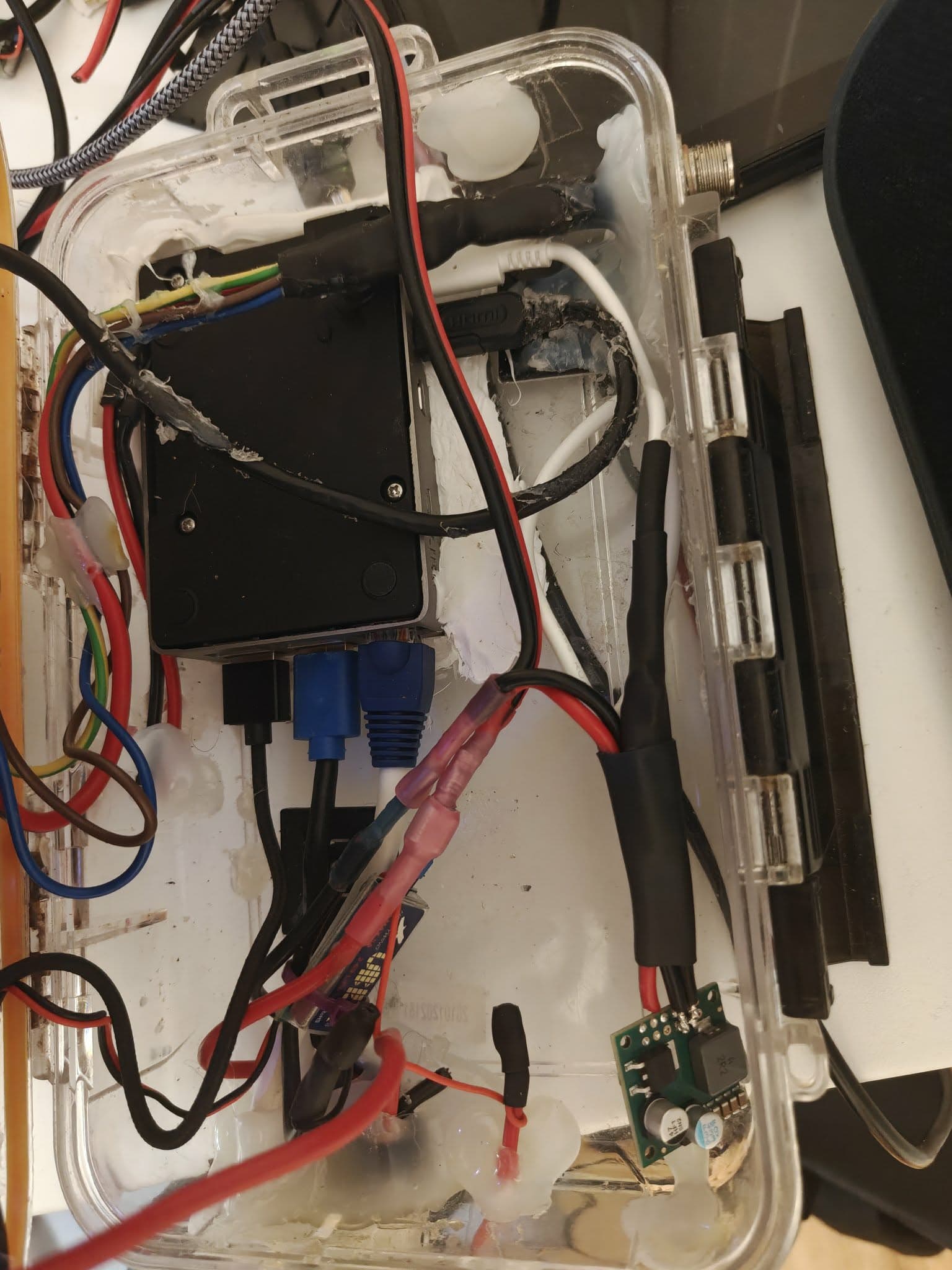
I have a couple of Pi’s in my boat running stuff like Home Assistant (relays that control just about everything), SignalK and media (4 TB disk with mostly my own ripped music, around 200K tracks). I upgraded to a Pi 5 8G RAM a couple of weeks ago, much because the Pi 4 was a bit slow when changing and searching for music because of the size of the library. I ordered a Pololu D36V50F5 from a German seller on eBay after reading about it here in this forum in a post from 2024 and assuming that would be good enough for the Pi 5. The cable from the step-down to the Pi is an USB-C taken from a Pi 4 wall wart, since powering with the GPIO pins gave constistently low voltage warnings. I am using usb_max_current_enable=1 in config.txt so the Pi assumes 5.5 A.
But the voltage shown on vcgencmd pmic_read_adc EXT5V_V is far from what I had hoped for. I have had to use two active USB 3 hubs, one for the SSD (which is rather power hungry), or I would still get those low voltage warnings. And I have another one for the USB wifi dongle, an Asus USB-AC68 with a Realtek RTL8814AU chip. Still I get from high 4.7V to low 8.5V under network load, and that seems very low, compared to the consistent 5.1V that I am getting from a Pi 5 wall wart on my other Pi 5’s.
I have soldered on both pin rails, and I am using dual DuPont connectors with two short cables soldered to regular 12V cables on both input and output, + and ground.
I have the same problem on the boat’s 12V system which (in reality is around 13.5-14.7V, depending on if the boat is docked with the charger connected or the motor is running) as I have on a laptop PSU that I’m using for stuff like that, with 65 watts in 18,5V.
Is this to be expected from this setup, or is there something wrong here somewhere?
I see that daisychaining the two powered USB 3.0 hubs helps a bit, I’m getting from low to high 4.9V, most of the time around 4.95V when running a network and SD card intensive task (I use a DD copy of the MicroSD which I have in a USB hub/card reader for easy access to a network share to tax both the file system and the network at the same time). But should this tapdance really be necessary with the step-down that’s rated for 5.5A?
Hello.
I suspect there is a significant voltage drop across your wires when there is more current being drawn; USB adapters made for Raspberry Pi boards often output closer to 5.2V to try to compensate for the drop. Could you try measuring the voltage directly between the regulator’s VOUT and GND pins when your Raspberry Pi is reporting a low voltage warning?
Brandon
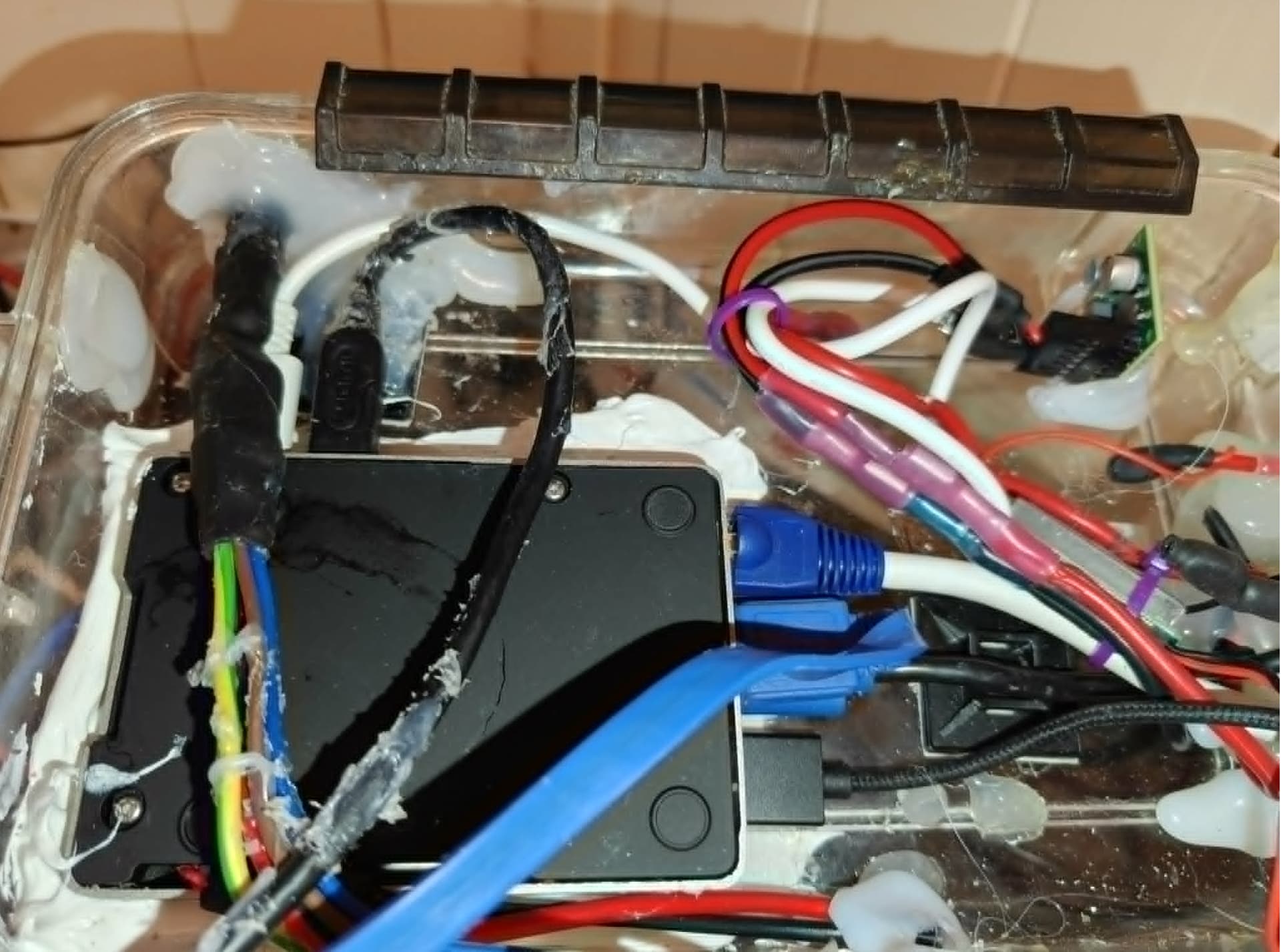
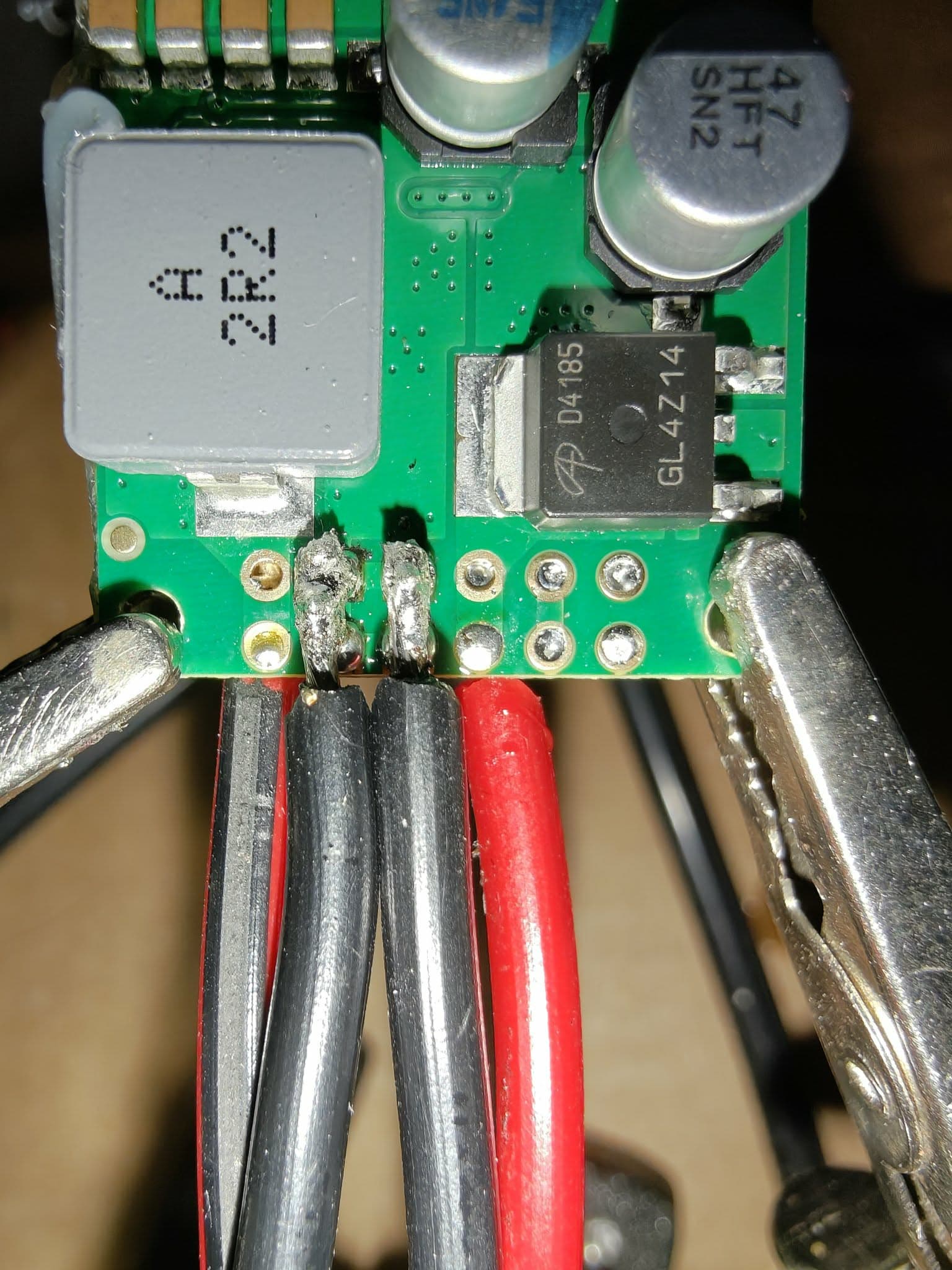
You are correct. I get 5.06-5.07 stable volts with my trusty, all though cheap, multimeter. Thats both with the Pi idle and when running a script that taxes the CPU to the max. Where do you think the power is lost? This is what my “masterpiece” of cabling and soldering looks like:
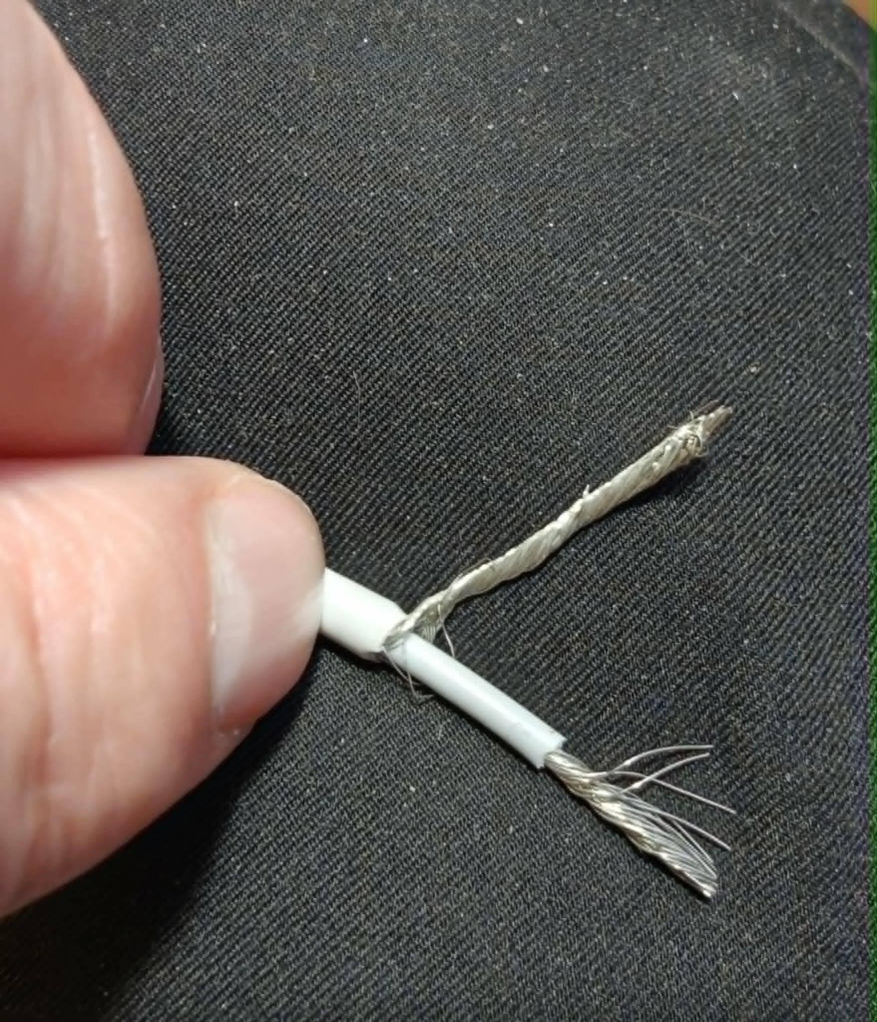
The white output cable is the cable from a Pi 4 wall wart, and both input and output have dual DuPonts, with short cables. The cable in the DuPonts are breadboard cables, so they are thin. Is that the problem, so I need to solder leaders the from the wall wart cable directly to the board? Or can it be that the cable from the wall wart isn’t thick enough? I doubt that, here’s the other side of the cut cable, I think the 25 cm or so of cable shouldn’t be a problem:
Edit: If you think it is the cable, I can get a 240 watt USB-C charcing cable at a local electronics store, maybe that will help?
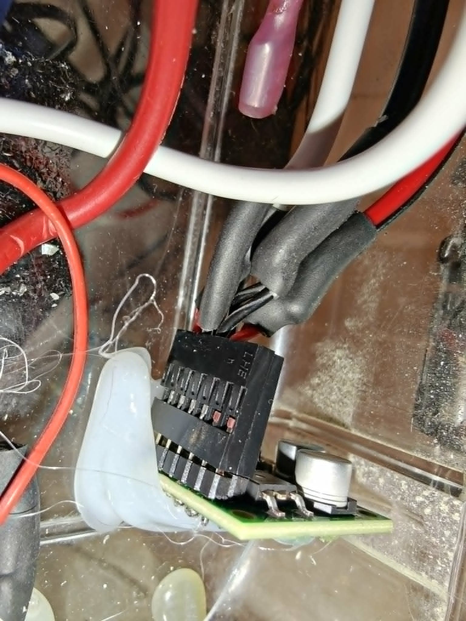
Edit 2: Looking at the picture I see that the plug has moved a bit up on the rail, but the business end should be well on the pin. Still, maybe best to solder on better cable?
Edit 3: Checked now with the original Pi 5 wall wart, and it was not able to run all the stuff in the box (the SSD is most power hungry, but there is an USB sound card, a serial device for communication with the boat’s system on NMEA2000 and a card reader as well) without the help of the original powered hub (not the one I added because of these power problems). With the powered hub the EXT5V never go below 5.1.
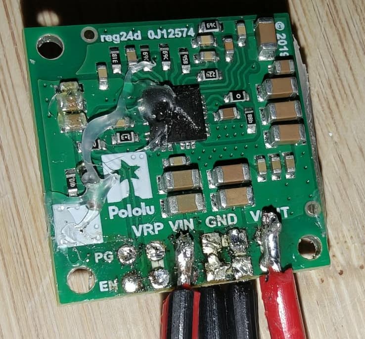
I figured I would try to solder on cables, and it went OK, but one thing: There is probably contact between the ground in and out, and I only messed it up worse using a desoldering wick. Am I right in assuming that it doesn’t matter because ground is ground, only plus wires differs? I’m no soldering master, so feel free to laugh all you want! 
The other side doesn’t look that bad, at least not in my eyes. It looks close, but there is not contact between ground and VIN:
If this is good enough I think I’ll use epoxy to lock it in. Normally I would use hot glue, but I’m afraid it will melt because of the heat from the board. Or maybe not? The hot glue I used to glue it to the plastic box hadn’t melted. Is it OK to encapsule the cables and the end of the board in hot glue?
The higher the resistance between your regulator and the load, the larger the voltage drop will be. So, the factors that contribute the most are probably your connectors and your wire (e.g. length, material, and thickness). However, depending on your setup, there might only be so much you can do.
Did the voltage drop get better after you added thicker wires? If it still didn’t improve enough, compensating with a higher voltage like the USB adapters I mentioned in my previous reply might be the only practical option. If you have the necessary skills and equipment for SMT soldering, we could give you the required details to modify the regulator’s output voltage.
To address some of your questions, the GND pins on the board are all connected internally, so it does not matter if the solder on your GND wires is touching. As far as hot glue, it will depend on your setup and whether or not it gets hot enough to re-melt, but otherwise using some to help with strain relief on the solder joints should generally be fine (but would also make it more difficult to rework if necessary). I would generally recommend not covering the components in hot glue though, since that would probably reduce the heat dissipation.
Brandon
Thanks again for answering! The voltage got visibly better with the wires soldered directly on, and no DuPont connectors and breadboard cable. Under network load and full CPU load I see quite consistently 4.97, never below 4.96. Consistently above 5 without the load. So I think that should be good enough.
Using an AC USB PSU is a non-starter here, I do not want anything above 12 volts in an open aluminum boat. I used shrink tube to link the wires together as strain relief, and I’ll hot glue the wire assembly to the inside of the box, so nothing should be able to move. The angle should help with heat dissipation.
I think I’ll try to leave well enough alone, even if it’s against my nature not to try to get it as close to perfect as possible…  Thanks for the help and tips!
1 Like
This Pololu discussion is useful here. It describes a nearly identical Raspberry Pi problem. Measuring voltage at several points. Measure both converter output and Pi input. This reveals where the voltage actually drops. Pololu also mentioned capacitors for brief transients. The case in the old thread ultimately involved cable and plug quality. That makes your connectors worth investigating carefully. This Electrical Wire Connectors Types guide helps. It covers contact resistance, crimping, ratings, and vibration. Your boat environment makes those factors especially important. I would test directly at the Pi’s USB-C. Then compare readings under identical network loads
Thanks, but it has now been working perfectly for a week, so I believe it’s as fixed as I need it to be. EXT5V stays just over 5V, 5.0x without full load, and just below, 4.9x, on full load.
1 Like