Line Follower Problem (Qtr 8Rc - L298N)

Hi…
I am trying to make a linefollowing robot and I am using the Pololu QTR-8Rc.
The materials I use:

  • QTR 8 RC (6 sensors used)
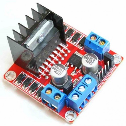
  • Pololu L298N Motor Control
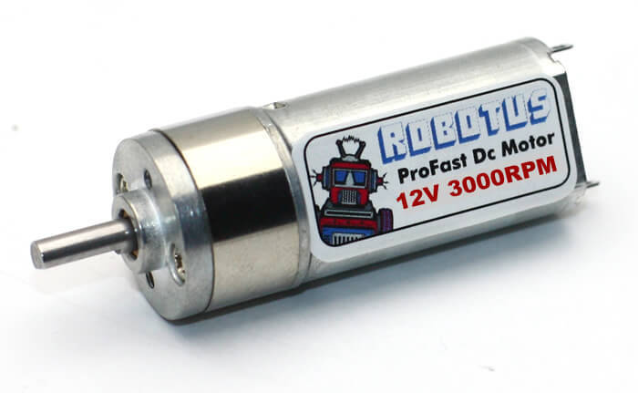
  • 2 robotus profast 12v 3000 rpm Motors

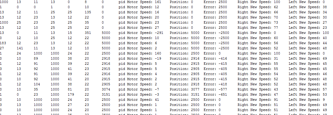
Screen Preview attached… Does not follow the line Please Help :confused:

My Code :

#include <QTRSensors.h>
#define Kp .2 
#define Kd 6.1
#define Ki 0.0015 
#define maxRightSpeed 100 
#define maxLeftSpeed 100 
#define defaultRightSpeed 50 
#define defaultLeftSpeed 50  
#define numberOfSensors  6     
#define TIMEOUT       2500  
#define EMITTER_PIN   2  
#define rightMotorForward 8
#define rightMotorBack 9
#define PWM_RIGHT 3
#define leftMotorForward 4
#define leftMotorBack 5
#define PWM_LEFT 6
#define STBY 13
QTRSensorsRC qtrrc((unsigned char[]) {  19,18,17,16,15,14} ,numberOfSensors, TIMEOUT, EMITTER_PIN); 
unsigned int sensorValues[numberOfSensors];

/* ...... S E T U P ...... */
void setup()
{
/* OUTPORT PORT DEFINE. */
                  pinMode(rightMotorForward, OUTPUT);
                  pinMode(rightMotorBack, OUTPUT);
                  pinMode(PWM_RIGHT, OUTPUT);
                  pinMode(leftMotorForward, OUTPUT);
                  pinMode(leftMotorBack, OUTPUT);
                  pinMode(PWM_LEFT, OUTPUT);
                  pinMode(STBY, OUTPUT);

/* CALIBRATE START. */
                  delay(500);
                  pinMode(13, OUTPUT);
                  digitalWrite(13, HIGH);   
                  for (int i = 0; i < 100; i++)
                  {
                    qtrrc.calibrate();
                  }
                  digitalWrite(13, LOW);
                  Serial.begin(9600);
}
/* ...... S E T U P    END...... */

                  int previousError = 0;
                  int previousIntegral = 0;
/* WHITE/BLACK DEFINE.. */
                  bool isWhite=0;
                  bool isBlack=1;


/* ...... L O O P    CODE START ...... */
void loop()
{
/* PRINT SENSOR VALUES... */
                    unsigned int position1 = qtrrc.readLine(sensorValues);
                  for (unsigned char sayac = 0; sayac < numberOfSensors; sayac++)
                  {
                    Serial.print(sensorValues[sayac]);
                    Serial.print('\t');
                  }
                  Serial.print(position1); //
                  Serial.print('\t'); 
/* END PRINT. */

/* PID... */
                  unsigned int sensors[6];
                  int position =qtrrc.readLine(sensors,QTR_EMITTERS_ON,isWhite); /* <<<<<<< WHITE ROAD BLACK LINE  */
                  int error = 2500- position;
                  int Integral = error+previousIntegral;
                  int speedOfMotor = (Kp * error)/100 + (Kd * (error - previousError))/100 + Ki * Integral;
                  previousError = error;
                  previousIntegral=Integral;
/* PID END... */

/* NEW MOTOR SPEED... */
                  int speedOfRight = defaultRightSpeed + speedOfMotor;
                  int speedOfLeft = defaultLeftSpeed - speedOfMotor;

/*OPTIMIZED MOTOR SPEED... */
                  if (speedOfRight > maxRightSpeed ) speedOfRight = maxRightSpeed; 
                  if (speedOfLeft > maxLeftSpeed ) speedOfLeft = maxLeftSpeed; 
                  if (speedOfRight < 0) speedOfRight = 0; 
                  if (speedOfLeft < 0) speedOfLeft = 0; 


/* PRINT NEW VALUES... */
                  Serial.print("pid Motor Speed: ");
                  Serial.print(speedOfMotor);
                  Serial.print('\t');
                  Serial.print("Position: ");
                  Serial.print(position);
                  Serial.print('\t');
                  Serial.print("Error: ");
                  Serial.print(error);
                  Serial.print('\t');
                  Serial.print("Right New Speed: ");
                  Serial.print(speedOfRight);
                  Serial.print('\t');
                  Serial.print("Left New Speed: ");
                  Serial.println(speedOfLeft);
                  delay(500);


/* NEW SPEED WRITE... */
                  digitalWrite(rightMotorForward, HIGH);
                  digitalWrite(rightMotorBack, LOW);
                  analogWrite(PWM_RIGHT, speedOfRight);
                  digitalWrite(leftMotorForward, HIGH);
                  digitalWrite(leftMotorBack, LOW);
                  analogWrite(PWM_LEFT, speedOfLeft);

}
/* ...... L O O P   E N D ...... */


Hello.

I am sorry you are having trouble getting your robot to follow a line. Can you more specifically describe how it is failing to follow a line? It would help if you post a link to a video that shows the behavior you are getting.

-Jon

thank you for taking the time with me…
I’m testing at the desk. I’m trying black line on white paper. Left-Right Motor works perfectly. But it does not work on the black line on the white ground. Does not follow the line, drawing circle…
I will send a video tomorrow…
Thanks…

Hi JonathanKosh,

I added video and new code :

This code is working.
but it does not follow line when the speed is increased (M1_MAX_SPEED,M2_MAX_SPEED)
Is this problem due to incorrect KP and KD values?

#include <QTRSensors.h>
#define KP 0.5
#define KD 0
#define M1_MAX_SPEED 80
#define M2_MAX_SPEED 80
#define M1_DEFAULT_SPEED 50
#define M2_DEFAULT_SPEED 50
#define MIDDLE_SENSOR 4, 5
#define NUM_SENSORS  6     // number of sensors used
#define TIMEOUT       2500  // waits for 2500 us for sensor outputs to go low
#define EMITTER_PIN   2     // emitter is controlled by digital pin 2
#define DEBUG 1 // set to 1 if serial debug output needed
#define rightMotor1 8
#define rightMotor2 9
#define rightMotorPWM 3
#define leftMotor1 4
#define leftMotor2 5
#define leftMotorPWM 6
#define motorPower 8
QTRSensorsRC qtrrc((unsigned char[]) {  14, 15, 16, 17, 18, 19} ,NUM_SENSORS, TIMEOUT, EMITTER_PIN);
unsigned int sensorValues[NUM_SENSORS];
void setup()
{
  pinMode(rightMotor1, OUTPUT);
  pinMode(rightMotor2, OUTPUT);
  pinMode(rightMotorPWM, OUTPUT);
  pinMode(leftMotor1, OUTPUT);
  pinMode(leftMotor2, OUTPUT);
  pinMode(leftMotorPWM, OUTPUT);
  pinMode(motorPower, OUTPUT);
  manual_calibration(); 
}
int lastError = 0;
int  last_proportional = 0;
int integral = 0;
void loop()
{
  unsigned int sensors[6];
  int position = qtrrc.readLine(sensors);
  int error = position - 2500;
  int motorSpeed = KP * error + KD * (error - lastError);
  lastError = error;
  int rightMotorSpeed = M2_DEFAULT_SPEED + motorSpeed;
  int leftMotorSpeed = M1_DEFAULT_SPEED - motorSpeed;
    if (rightMotorSpeed > M1_MAX_SPEED ) rightMotorSpeed = M1_MAX_SPEED; // limit top speed
  if (leftMotorSpeed > M2_MAX_SPEED ) leftMotorSpeed = M2_MAX_SPEED; // limit top speed
  if (rightMotorSpeed < 0) rightMotorSpeed = 0; // keep motor above 0
  if (leftMotorSpeed < 0) leftMotorSpeed = 0; // keep motor speed above 0
   {
  digitalWrite(motorPower, HIGH);
  digitalWrite(rightMotor1, HIGH);
  digitalWrite(rightMotor2, LOW);
  analogWrite(rightMotorPWM, rightMotorSpeed);
  digitalWrite(motorPower, HIGH);
  digitalWrite(leftMotor1, HIGH);
  digitalWrite(leftMotor2, LOW);
  analogWrite(leftMotorPWM, leftMotorSpeed);
}
}
void manual_calibration() {
  int i;
  for (i = 0; i < 250; i++)  // the calibration will take a few seconds
  {
    qtrrc.calibrate(QTR_EMITTERS_ON);
    delay(20);
  }
  if (DEBUG) { // if true, generate sensor dats via serial output
    Serial.begin(9600);
    for (int i = 0; i < NUM_SENSORS; i++)
    {
      Serial.print(qtrrc.calibratedMinimumOn[i]);
      Serial.print(' ');
    }
    Serial.println();
    for (int i = 0; i < NUM_SENSORS; i++)
{
  Serial.print(qtrrc.calibratedMaximumOn[i]);
  Serial.print(' ');
}
Serial.println();
Serial.println();
  }
}

The PID coefficients in a feedback control loop are tuned to work for that specific system. So, if any changes are made to that system, like increasing the speed in your line following robot, the PID coefficients will likely need to be tuned again. The coefficients should be easier to tune with smaller changes. So, your tuning process should be: start with the line following code that you know works well, increase the speed by a small amount (e.g. if your robot is working well with a default speed of 50, try using a value of 53 or 55, as opposed to trying a much larger value like 75 or 80), observe the behavior of your robot as it follows the line, make a small adjustment to your coefficients based on the performance, and test the robot on the line following course again. Once you get your robot following the line as perfectly as you can at the current speed, then you can try increasing the speed again by a small amount and repeating the tuning process.

By the way, since your robot is following the line okay without KD (i.e. KD currently has a value of zero), it looks like your PID controller is probably ready to use a derivative term to make it follow the line even more smoothly before starting to increase speed. You can get a good idea of how to start adding KD to your controller by reading this post by Ben.

-Jon

Do you have a connection diagram?

If u solved the problem, can u send the code?

Thanks…

do you have a connection diagram?