
Hello
I have made a line follower using these components:
- L298N Motor Shield Driver
- Arduino Nano
- QTR-8RC Reflectance sensor array
- 2x DC Geared Motor (3-6V)
- 9V battery
I’ve made some connections between everything and everything looks like its well-connected, however I can’t get my sensor to recognize anything. (I’m using only 5 of the 8 sensors available)
I need some help figuring out a code that could make my Line follower work and the respective circuit diagram (or some code that works using the connections I have on my Line follower)
Circuit Diagram I am using:
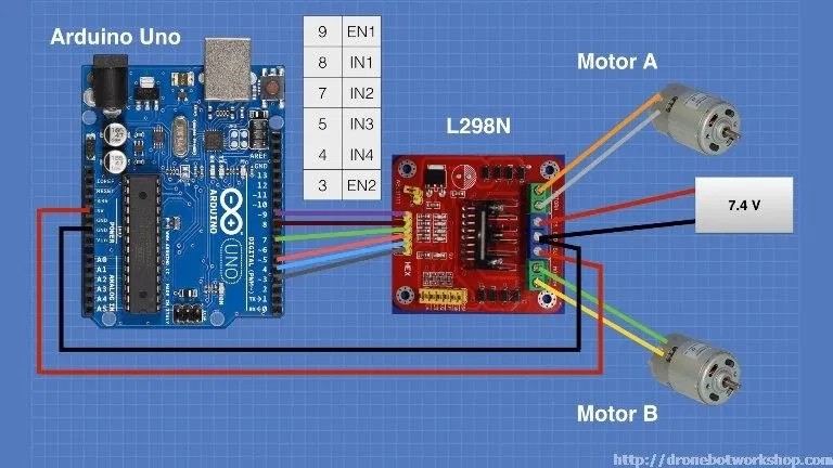
Additionaly, The sensor array (pins n. 2, 3, 4, 5, 6) are connected respectively to arduino’s analog pin (A0, A1, A2, A3, A4). Also the sensor’s GND and VCC pins are connected to the arduino’s GND and 5V pin.
The code I’m using (which isn’t working):
#include <AFMotor.h>    //Adafruit Motor Shield Library. First you must download and install AFMotor library
#include <QTRSensors.h> //Pololu QTR Sensor Library. First you must download and install QTRSensors library

AF_DCMotor motor1(1, MOTOR12_1KHZ ); //create motor #1 using M1 output on Motor Drive Shield, set to 1kHz PWM frequency
AF_DCMotor motor2(2, MOTOR12_1KHZ ); //create motor #2 using M2 output on Motor Drive Shield, set to 1kHz PWM frequency

#define KP 2 //experiment to determine this, start by something small that just makes your bot follow the line at a slow speed
#define KD 5 //experiment to determine this, slowly increase the speeds and adjust this value. ( Note: Kp < Kd)
#define M1_minumum_speed 150  //minimum speed of the Motor1
#define M2_minumum_speed 150  //minimum speed of the Motor2
#define M1_maksimum_speed 250 //max. speed of the Motor1
#define M2_maksimum_speed 250 //max. speed of the Motor2
#define MIDDLE_SENSOR 4       //number of middle sensor used
#define NUM_SENSORS 5         //number of sensors used
#define TIMEOUT 2500          //waits for 2500 us for sensor outputs to go low
#define EMITTER_PIN 2         //emitterPin is the Arduino digital pin that controls whether the IR LEDs are on or off. Emitter is controlled by digital pin 2
#define DEBUG 0

//sensors 0 through 5 are connected to analog inputs 0 through 5, respectively
QTRSensorsRC qtrrc((unsigned char[]) { A4,A3,A2,A1,A0} ,NUM_SENSORS, TIMEOUT, EMITTER_PIN);

unsigned int sensorValues[NUM_SENSORS];

void setup()
{
delay(1500);
manual_calibration();
set_motors(0,0);
}

int lastError = 0;
int last_proportional = 0;
int integral = 0;

void loop()
{
unsigned int sensors[5];
int position = qtrrc.readLine(sensors); //get calibrated readings along with the line position, refer to the QTR Sensors Arduino Library for more details on line position.
int error = position - 2000;

int motorSpeed = KP * error + KD * (error - lastError);
lastError = error;

int leftMotorSpeed = M1_minumum_speed + motorSpeed;
int rightMotorSpeed = M2_minumum_speed - motorSpeed;

// set motor speeds using the two motor speed variables above
set_motors(leftMotorSpeed, rightMotorSpeed);
}

void set_motors(int motor1speed, int motor2speed)
{
if (motor1speed > M1_maksimum_speed ) motor1speed = M1_maksimum_speed;
if (motor2speed > M2_maksimum_speed ) motor2speed = M2_maksimum_speed;
if (motor1speed < 0) motor1speed = 0;
if (motor2speed < 0) motor2speed = 0;
motor1.setSpeed(motor1speed);
motor2.setSpeed(motor2speed);
motor1.run(FORWARD);
motor2.run(FORWARD);
}

//calibrate for sometime by sliding the sensors across the line, or you may use auto-calibration instead
void manual_calibration() {

int i;
for (i = 0; i < 250; i++)
{
qtrrc.calibrate(QTR_EMITTERS_ON);
delay(20);
}

if (DEBUG) {
Serial.begin(9600);
for (int i = 0; i < NUM_SENSORS; i++)
{
Serial.print(qtrrc.calibratedMinimumOn[i]);
Serial.print(' ');
}
Serial.println();

for (int i = 0; i < NUM_SENSORS; i++)
{
Serial.print(qtrrc.calibratedMaximumOn[i]);
Serial.print(' ');
}
Serial.println();
Serial.println();
}
}
Thanks in advance!