First and foremost, I am a newbie. I have enjoyed reading the resources listed and the grey matter between my ears and starting to “get” some of it
One project I am working on is a linear actuator type lifter. I am using some Vex pieces that I am told will work with standard motor controllers. Essentially I have the motor, motor bracket, rack and pinion. Simply put, I would like the motor and bracket assembly to rise to set position by the limit switch and stop. Then, reverse polarity and it descend to the lower limit switch position. Just like the Firgelli linear actuators I have for other portions of my robot build.
The reason for the rack and pinion is it will fit inside the enclosure I have where as the smallest linear actuator will not.
I would like to control that up and down command via the motor controller, say a Dimension Engineering Syren or the devices available here (I happen to have two of the Syrens)
Having never played with limit switches but having read as much as I could find on various searches, I am intrigued what is needed to make this work.
Thanks in advance for suggestions and teaching a new guy!
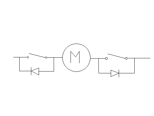
I have no experience with the Syrens, so I do not know if they are designed to accept limit-switch inputs directly. One solution is to use the limit switches to directly control power to the motor. You can do this with two normally closed, or NC, switches (one for each end of motion), each with a diode in parallel oriented so that the switch only disables motor operation in the direction that would break something. Can you picture this, or do you need me to draw up a quick schematic? For this solution, you need switches and diodes that are capable of carrying the full motor current. I’m pretty sure this is how the linear actuators we sell work.
Perhaps an easier option would be to use one of our Simple Motor Controllers, which have built-in support for limit switches. In this case, you could use pretty much any switch since it would not have to carry the motor current. Basically, you would just connect your two switches and then configure the controller over USB using our Simple Motor Control Center software.
The two switches are normally closed, so current can flow through the motor in both directions. When the motor hits a limit, one the corresponding switch opens, and current flow is restricted by the diode to only one direction (the direction that lets the motor to back away from the limit).
Do you sell limit switches? I believe the Vex ones should work fine but just in case.
I see the motor controllers from your previous reply.
The Vex 393 motor specs are as follows…
Our snap-action switches have both NC (normally closed) and NO (normally open) connections, and several of them are rated at up to 5 A, so they would work in the diagram I drew. We do not sell diodes, but these are generic parts you can get in quite a few places, such as digikey.com.
If you want to use one of our controllers instead, I would suggest the Simple Motor Controller 18v7. You could use any switch you want for your limit switches, and you wouldn’t need the diodes.
Sorry, I have fixed the link. You might also be interested in knowing that we’ll be having some pretty big discounts on our Simple Motor Controllers during our upcoming Black Friday sale.
It’s pretty much just how it sounds. A normally open switch only completes the circuit when the switch is pressed. A normally closed switch conducts as long as the switch is not pressed (the act of pressing breaks the circuit).
I think you’re going to have trouble getting it to perform an action on power off. Is it not possible to make it lower itself and then manually turn the power off with a separate switch? Otherwise, you need to come up with a way for the device to turn itself off (you might consider using one of our pushbutton power switches for this (these will also be part of our Black Friday sale).
The max relay current for that is 1 A, so I don’t think it will work for you (your motor might draw as much as 3.6 A). We have a similar product that can handle up to 15 A (and, unlike the unit you have, the required flyback diode is built-in). But neither this nor the unit you linked to allows the device to shut off its own power, which you will require if you want something to perform a certain action when commanded to power down. The pushbutton power switch I linked to gives a device the ability to turn off its own power.
So knowing I need to move this motor up and down to adjustable limits, what would be your suggestion to make this work with the referenced motor controller? (Which I intend to purchase with the Black Friday link you shared). If there is anything else I should add to my shopping cart to make this work, please let me know
That ultimately depends on what kind of interface you want. If you want a complicated interface, you will likely need a microcontroller to process the user input and generate the appropriate serial commands for the motor controller.