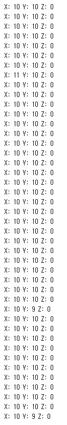
I am looking at the L3GD20 data stream from the L3GD20 3-Axis Gyro Carrier with Voltage Regulator board and it seems very noisy. With no movement, here is a sample of the output from the example program "serial"
I work with gyros a lot and understand that they drift, but this is not a steady drift, the readings jump all over.
I realize that this is raw data and that when scaled to dps the noise is not so bad, but still seems high. Perhaps I am using the wrong conversion? I am using full scale sensitivity (2000 dps, 70 mdps/digit) so am using a 0.07 conversion from raw data to degrees per sec. Is that correct?
I noted that if I average the readings, they are around a common mean. Is this noise level normal for this sensor?
G X: -17 Y: -56 Z: -150
G X: -57 Y: -64 Z: -212
G X: -43 Y: -72 Z: -188
G X: -27 Y: -76 Z: -151
G X: -19 Y: -74 Z: -221
G X: -25 Y: -29 Z: -137
G X: -40 Y: -54 Z: -155
G X: -40 Y: -80 Z: -198
G X: -15 Y: -63 Z: -174
G X: -36 Y: -75 Z: -155
G X: -62 Y: -70 Z: -143
G X: -46 Y: -76 Z: -183
G X: -39 Y: -50 Z: -187
G X: -15 Y: -71 Z: -159
G X: -7 Y: -60 Z: -163
G X: -9 Y: -72 Z: -170
Hello. The noise level in your data looks normal to me.
Yes, that is correct.
The “steady drift” you are referring to is probably what you see when you integrate the rotations from the gyro, but you wouldn’t see it when you look at the raw readings.
There will generally be some noise and some zero-rate offset for sensors like this. You really have to convert it to some human-understandable unit (degrees per second) to evaluate it. You can look in the sensor’s datasheet to get an idea of how much offset and how much noise is typical. You can find the datasheet by going to the pololu.com product page for your device and opening the Resources tab (below the price and short description).
If you still think that you are getting too much noise or too much of an offset from your device, please provide us with the following information:
The configuration settings you used on the device. (Different settings can result in different amounts of noise and offset.)
15-50 sets of raw readings from the device, taken while it is stationary.
For every axis you are concerned about, the standard deviation and average of the readings from that axis. You can use a spreadsheet program to calculate this.
The standard deviation and average, converted to human units. For a gyro, convert to dps (degrees per second).
The relevant information from the datasheet that makes you think your readings are atypical.
I have been playing with the ST eval board of this gyro.
Has anyone else but me noticed that ambient light level causes the output to drift? Mine sees a y-axis zero rate shift from 700 counts to 380 going from a lighted room to dark. Discovered by accident but totally reproducible.
We attempted to duplicate your results, but could not. We obtained data while the sensor was exposed to office lighting, natural sunlight, and inside an enclosed container. Could you please tell us more about your setup?
The L3GD20 is configured for 250 d/s and I am using the FIFO at a watermark of 16 readings, at which I read and average. I then run a 50 reading moving average filter to establish the zero-rate level. Here is the output of that moving average filter as I cover and uncover the board with my hand in a partially sunlit room.
Thank you for sharing your settings. When I adjusted my setup to more closely match yours, I was able to notice a difference in the readings depending on whether the board was in direct sunlight or shaded by my hand. However, it is not clear to me whether the variation is due to the light itself or just the temperature difference between light and shade.
I have since looked at the readings before I the MA filter and yes it is still responding to light. I will get another sample and see if its the same. In the meantime I covered the chip with a piece of black electrical tape and the effect is diminished greatly (but not gone). I see a big effect from just turning the room lights off and on.
Is it useful to apply a moving average filter to this sensor? I have a ST evaluation board for this sensor and the data which I am getting is offcourse raw as mentioned in the sample code. But my question is that what could be the best way to reduce this noise either by a filter or a set-up.?
Also, does anyone has any knowledge about the IMU and micro magnetometers like MicroMag3 and Honeywell HMC5883L implementation with any board. Any example codes for that. I have an IMU from Analog devices. Sorry for asking this but I am very new to this electrical field. Please help.
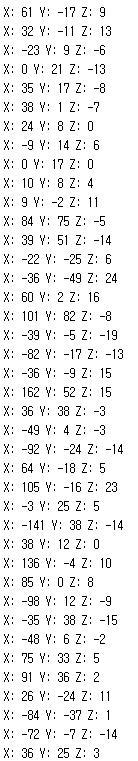
I got the following readings with and without movement. Can anyone advise me whether to apply the moving average filter to it or the readings or fine enough.?
Some variation is normal. Are you using our L3GD20 breakout board? From the schematic you posted, it looks like you might have designed your own board. What are you using to communicate with the gyro? Could you post your code and tell me how you are setting the control registers? Could you also post pictures of your setup?
Thanks. I’m sorry not buying L3GD20 breakout board, just want to do it by myself. In fact the target of this project is to use gyroscope and odemeter to make vehicle navigation testing. That be commonly konwed as deadreckon. In my project, gyroscope connected with microcontroller of stm32 serial product and communicate with I2C Interface. In the other side, odemeter give running distance, so I can get changed degree and displacement and then deduce the new position with combination of that two part of information.
In my project, I want to make deadreckon with frequency of 10HZ. so gyroscope signal was sampled in 10 times per second. fullscale was chosed to be 250dps and ODR is 190HZ. In order to statisfy designed output frequency, I set watermark as 19, so data was reading when watermark interruption happened. I write code in IAR, The code is listed below:
By the end, sorry to get pictures of my setup because the size of board is so small. Can you find some quesiton from code? May be some problem existed when setting control register of gyroscope. Very appreciate for you help!
You might refer to our Arduino libary for the L3G gyros to see how we set the control registers. By the way in your first post, it looks like some of the readings repeat. I suspect that you are taking readings faster than what the device is sampling at.
yeah, you are right, I have also notice that seems to read FIFO repeatly. This app is just a test version and only run in one task in ucos like a singl thread and reading speed is too fast. Thanks for your tips. I will check Arduino libary later. Now, I want ask another question:
From some other’s answer I find there is more noise existed in my data, at least seems to be like that in my opinion. so I want to know, If I get some new data later, how can I decide it’s good or bad data? whether the noise is distributed in normal level? I try to get standard noise range from datasheet but looks like no releated information has been detailed, so how to do it?
All the information we have for the L3GD20 gyro is from its datasheet. You should look at the digital zero-rate level and the rate noise density specifications to determine if the noise you are getting is within spec. By the way, as mentioned earlier in this thread, you might implement a moving average filter to smooth out the readings.