Hi, I’ve been trying to power the Jetson Nano with various 5V voltage regulators from Pololu with no success. I was wondering if you guys have a Nano on hand, and have tried powering one with the Pololu regulators? I’m wondering if there is something in the electrical design of the jetson nano boards that conflicts with pololu’s regulators that I don’t quite understand.
I’ve tried the following products from Pololu:
5V 5A D24V50F5
5V 9A D24V90F5
I am powering the Nano via pins 2,4 for 5V, and 6, 9 for GND as noted here. The forum post claims that each pin takes up to 3A, but that is actually incorrect and according to the Jetson Nano manual/datasheet, each pin should be expected to take in 2.5A, which should be inline with both regulators I tried from Pololu. Additionally, when I try powering the nano directly from a benchtop power supply, I see that the current averages 0.5A-1A, which should be well within the limits of both regulators. I unfortunately don’t have an oscilloscope on hand to inspect the voltage at a high resolution.
In all cases when powering from the regulator, the Nano would boot up, and after a few seconds shutdown. The time it takes to shutdown is always the same, and I think it is the same time as when the USB peripherals receive power. I have tried putting a 1uF and 10 uF capacitor between 5V/GND, but that didn’t do anything.
Hello.
Can you try monitoring the output voltage of the regulator with your multimeter (or a oscilloscope if you can get access to one) to see what happens when the Jetson Nano shuts down? Does disconnecting all of the USB peripherals you have connected change the result?
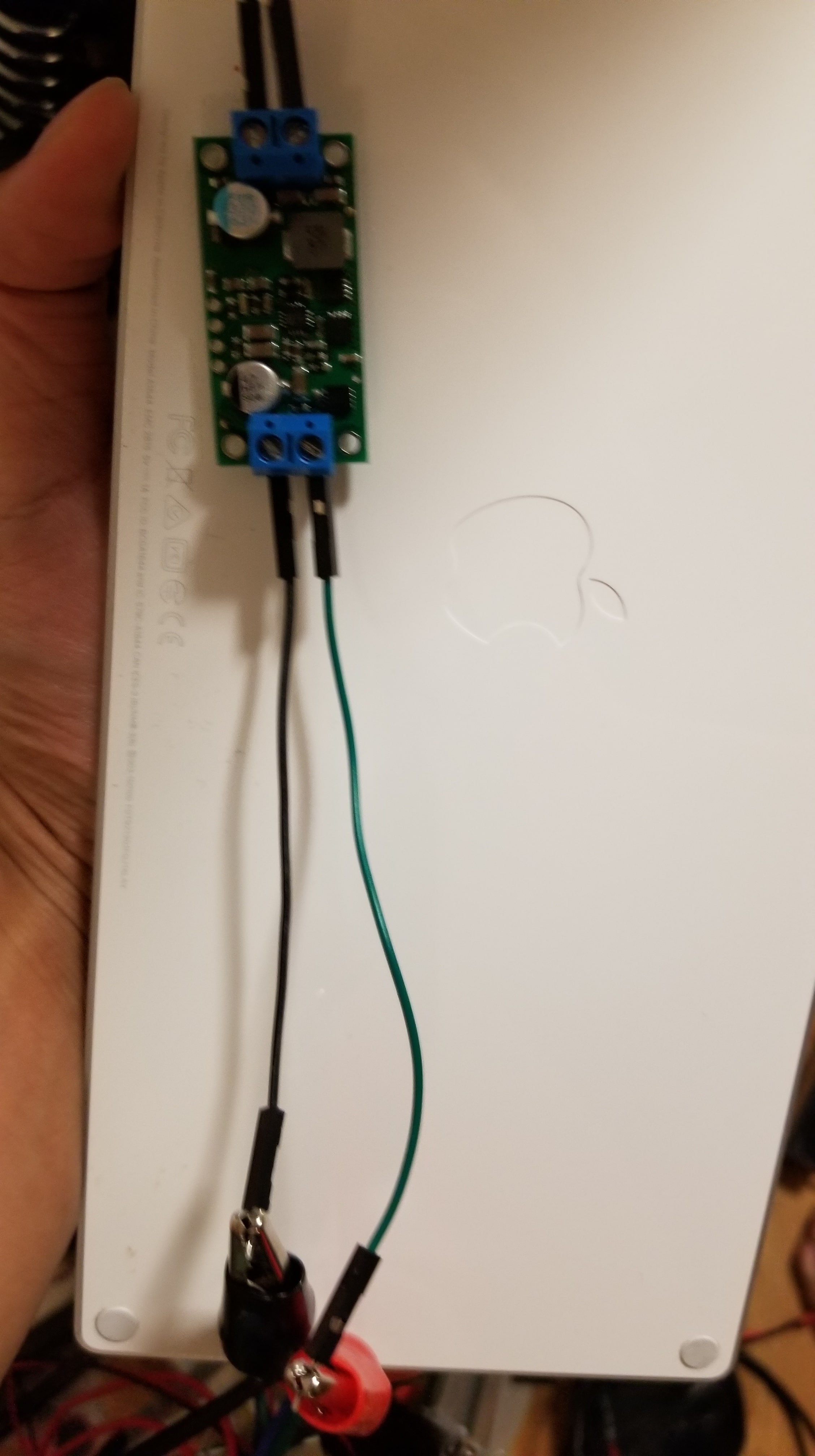
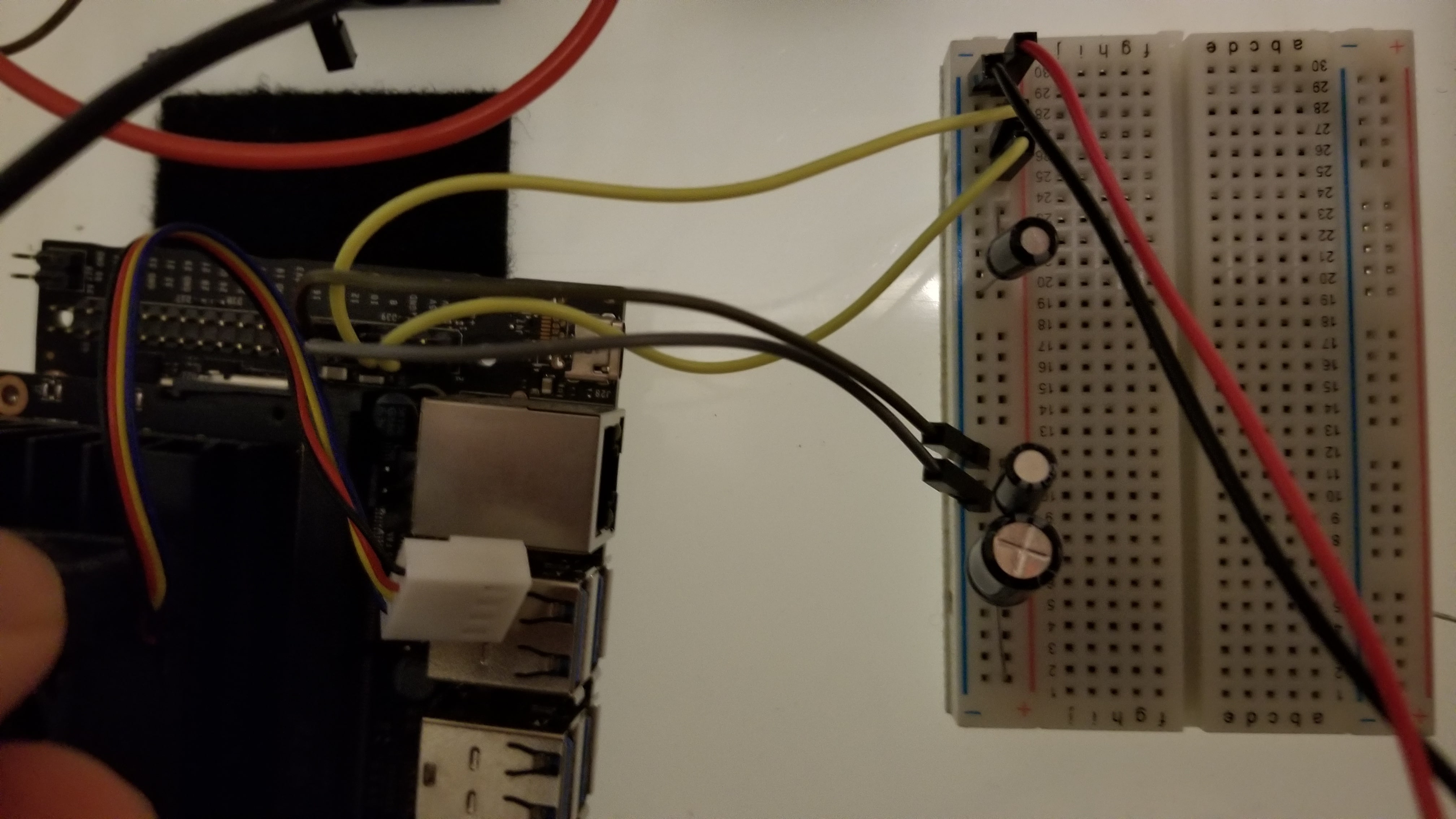
Could you also post some pictures of your connections and explain how you are powering the regulators?
- Patrick
Removing all USB peripherals, I observe the following:
So inspecting it more carefully with a multimeter, I can see that the voltage first starts at ~5V as expected, then after a few seconds drops to ~4.65-4.7V, until the nano shutsdown a few seconds later. The nano shuts down almost exactly always 12 seconds from boot (I’m assuming some certain circuits, including the USB hub, get’s power during this time. After the nano shutsdown, or when not connected, the regulator is at 5V. Important thing to note is that the nano is not expected to shutoff unless the voltage is below ~4.2V as noted by nvidia staff here.
My electrical set up is a bit messy so I don’t think a picture would be helpful. However, here is my setup:
- The benchtop power supply is outputting 15V, 10A limit to the voltage regulator Vin. Obviously this is constant voltage since the regulator is not drawing 10A
- The Vout of the regulator goes into the power rails for a breadboard. (I have already tried a different breadboard/busbar)
- Two capacitors (1uF, 10uF as mentioned above) are across the +/- of the power rails.
- Two positive wires goes from the positive rail to pins 2,4 on the nano. Two negative wires goes from the negative rail to pins 6, 9 on the nano.
The setup works if I replace the Vin to the rails with a 5V from the benchtop directly (with and without the capacitors). Also as mentioned, both the Pololu regulators is not able to power the nano.
Thank you for the additional information. I think pictures would still be helpful since they could reveal something we are not thinking about yet. Also, its never good to have a messy setup anyway, so maybe this gives some extra motivation to organize your setup’s wiring a little better which will probably help in the long run.
The post you linked to indicates that 4.2V is the point where the Jetson Nano is guaranteed to turn off, but it will likely turn off at higher voltages. It is good practice to make sure the supply voltage for a controller is not dropping too much (e.g. no more than around 5%), so I think we should aim to prevent your regulated output voltage from dropping below the 4.75V VDD_IN minimum value. Where were you measuring the regulator output voltage, at the regulator or at the Nano’s pins?
We do not expect the 10µF capacitor to help too much. Could you try something larger, like 100µF or more?
Since the Nano can draw up to a few amps you could be getting a significant voltage drop across your breadboard and wires. (Breadboards in particular are not appropriate for handling that much current.) Can you try powering your Nano without going through the breadboard and minimize your wire length?
- Patrick
we should aim to prevent your regulated output voltage from dropping below the 4.75V VDD_IN minimum value
Good point.
Where were you measuring the regulator output voltage, at the regulator or at the Nano’s pins?
I’m measuring it at the capacitor pins, but even measuring the voltage close to the wires that go into the Nano doesn’t make a difference. And as I mentioned, I’ve tried a different busbar alltogether.
We do not expect the 10µF capacitor to help too much. Could you try something larger, like 100µF or more?
I tried adding an additional 100µF and instead of the voltage dropping to ~4.7v, it drops to ~4.8. However, the effects are the same in terms of shutting down at 12s.
Can you try powering your Nano without going through the breadboard and minimize your wire length?
I don’t think this is the issue since I don’t see any voltage drop across the breadboard rails, and measuring the voltage as close to the wires that goes into the nano as possible produces the same results.
If you are measuring the voltage at the Jetson Nano’s inputs and they are holding over 4.75V, then we can only guess at why it is still shutting down after 12s, but it is hard to be confident whether or not that is actually the case just by measuring the inputs with a multimeter since you are unlikely to see brief voltage transients that way. Getting to the bottom of this will probably require looking at your setup with an oscilloscope so you can actually see what is going on. Is there any way you can get or borrow a scope?
Even aside from the current need, we strongly recommend investing in scope. You can get a decent one these days for a few hundred dollars and it will save you a lot of time and give you better understanding of your systems, which enables better designs, better margins of operation, etc. Without one, you are left mostly just guessing about what might be happening, which is not a great way to operate.
In the meantime, I would also suggest looking into your Jetson Nano’s startup code to see if you can find out anything more about what might be happening around 12s that way.
Alternatively, you could just try getting a regulator that uses a different IC, like our D36V50F5, to see if it might respond to whatever the Jetson Nano is doing better, but that is just a shot in the dark without knowing what is causing it to shutdown.
- Patrick
Hey Patrick, I got a scope, and found that the power supply drops to a minimum of 4.67V. The nano also pretty much shuts down after the voltage drops below 4.75 as you expected. As I mentioned, the nano typically only draws ~1A on boot up at 5V, so this should be within the performance range of the D24V90F5. I guess the solution here would be to add more capacitors to smooth the ripple? Could you give me some pointers as to how I could calculate the correct size of the capacitor given the waveform I have captured?
Using C = I * dU/dt
Should “I” be 9A (since that’s what the regulator is capable of)?
Should dU be 0.42V? (same as Vpp)
Should dt be the time between 5V and the start of the trough, or the end of the trough when the nano had shutdown and the regulator recovers to 5v?
I am glad to see you were able to get an oscilloscope!
There are all sorts of things going on with a system like this that will make it difficult to calculate how much capacitance you should add, so I would suggest a more iterative approach. Start by looking at how your setup acts when there are no extra caps, then test it with some of the caps you have readily available to see if it has any effect and how much. That should give give you a decent foundation to start iterating on.
- Patrick