I am experiencing an issue with my QTR-8RC sensor array when using it with an ESP32-VROOM-32U. Despite following the setup and calibration procedures, the sensor does not seem to be functioning correctly. Below are the details of my setup and observations:
Setup Details:
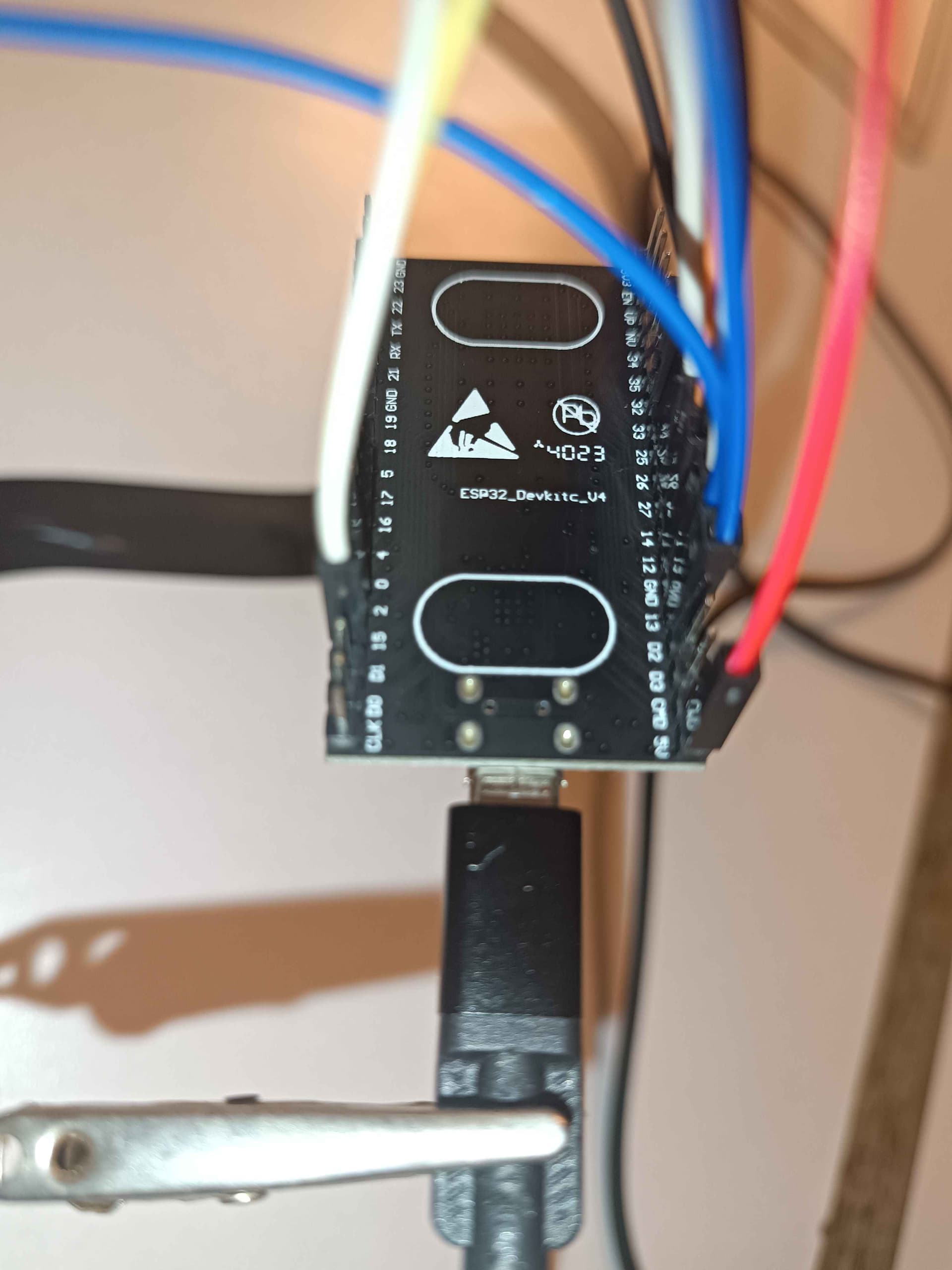
• Microcontroller: ESP32-VROOM-32U
• Power Source: MacBook Air M2
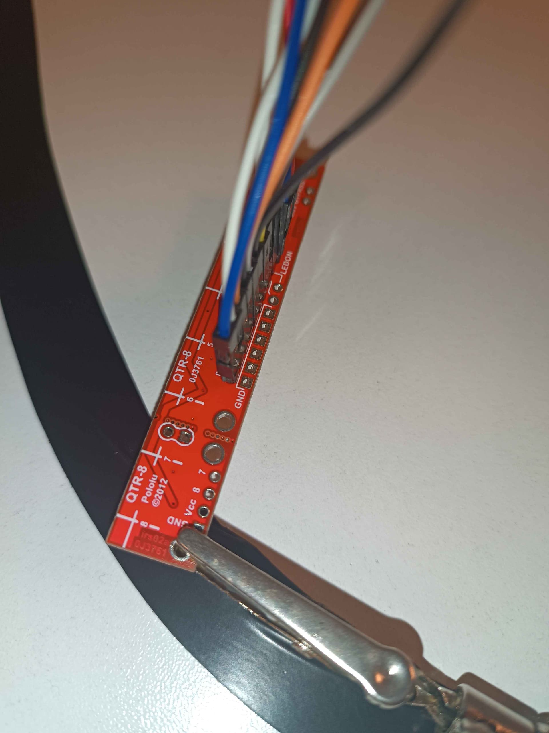
• Sensor Array: QTR-8RC (8 sensors)
• Connection Pins: 2, 12, 13, 14, 15, 26, 27, 32
• Emitter Control Pin: 2
Issue:
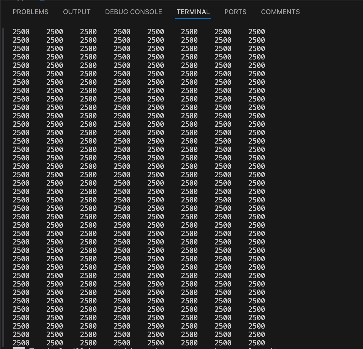
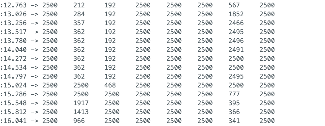
The sensor values do not seem to be consistent or correct. As shown in the attached output image, the sensor values remain at 0 or do not vary as expected. Consequently, the position readings and suggested directions (turn left, turn right) are not accurate. Here is a sample of the output I am seeing:
2500 2500 2500 2500 2500 2500 2500 158
2500 2500 2500 2500 2500 2500 2500 2500

0       0       0       0       0       0       0       1000    Position: 7000 - Turn left
0       0       0       0       0       0       0       1000    Position: 7000 - Turn left
0       0       0       0       0       0       0       1000    Position: 7000 - Turn left
0       0       0       0       0       0       0       1000    Position: 7000 - Turn left
0       0       0       0       0       0       0       1000    Position: 7000 - Turn left
0       0       0       0       0       0       0       1000    Position: 7000 - Turn left
0       0       0       0       0       0       0       1000    Position: 7000 - Turn left
0       0       0       0       0       0       0       1000    Position: 7000 - Turn left
0       0       0       0       0       0       0       1000    Position: 7000 - Turn left
0       0       0       0       0       0       0       1000    Position: 7000 - Turn left
0       0       0       0       0       0       0       1000    Position: 7000 - Turn left
0       0       0       0       0       0       0       1000    Position: 7000 - Turn left
Code:
Here is the Arduino code I am using for the setup and calibration of the QTR-8RC sensor array:
#include <Arduino.h>
#include <QTRSensors.h>

QTRSensors qtr;

const uint8_t SensorCount = 8;
uint16_t sensorValues[SensorCount];

void calibrateSensors(){} // implementation of the calibrateSensors function

void setup()
{
  // configure the sensors
  qtr.setTypeRC();
  qtr.setSensorPins((const uint8_t[]){2, 12, 13, 14, 15, 26, 27, 32}, SensorCount);
  qtr.setEmitterPin(2); // emitter is controlled by digital pin 2

  delay(2000); // It is 2000 for test it should be 500 ms for the actual robot
  // 2.5 ms RC read timeout (default) * 10 reads per calibrate() call
  // = ~25 ms per calibrate() call.
  // Call calibrate() 400 times to make calibration take about 10 seconds.
  for (uint16_t i = 0; i < 400; i++)
  {
    qtr.calibrate();
  }

  // print sthe calibration minimum values measured when emitters were on
  Serial.begin(9600);
  for (uint8_t i = 0; i < SensorCount; i++)
  {
    Serial.print(qtr.calibrationOn.minimum[i]);
    Serial.print(' ');
  }
  Serial.println();

  // print the calibration maximum values measured when emitters were on
  for (uint88_t i = 0; i < SensorCount; i++)
  {
    Serial.print(qtr.calibrationOn.maximum[i]);
    Serial.print(' ');
  }
  Serial.println();
  Serial.println();
  delay(10000); // It is 10000 for test it should be 1000 ms for the actual robot
}

void loop()
{
  // read calibrated sensor values and obtain a measure of the line position
  // from 0 to 5000 (for a white line, use readLineWhite() instead)
  uint16_t position = qtr.readLineBlack(sensorValues);

  // print the sensor values as numbers from 0 to 1000, where 0 means maximum
  // reflectance and 1000 means minimum reflectance, followed by the line
  // position (0 to 5000)
  for (uint8_t i = 0; i < SensorCount; i++)
  {
    Serial.print(sensorValues[i]);
    Serial.print('\t');
  }
  Serial.print("Position: ");
  Serial.print(position);
  Serial.print(" - ");

  // Determine direction based on the position of the line
  if (position < 1667) {
    // If position is in the left third, turn left
    Serial.println("Turn right");
  } else if (position > 3333) {
    // If position is in the right third, turn right
    Serial.println("Turn left");
  } else {
    // If position is in the middle third, go straight
    Serial.println("Go straight");
  }

  delay(1000); // It is 1000 for test it should be 250 ms for the actual robot
}