Hello
I am trying to establish serial communication between a raspberry pi and 3pi+ through UART. To do this, I removed the display to free up a pair of RX TX pins. I am able to send data from the 3pi+ to the Pi but I am unable to do the reverse (receive data from the Pi).
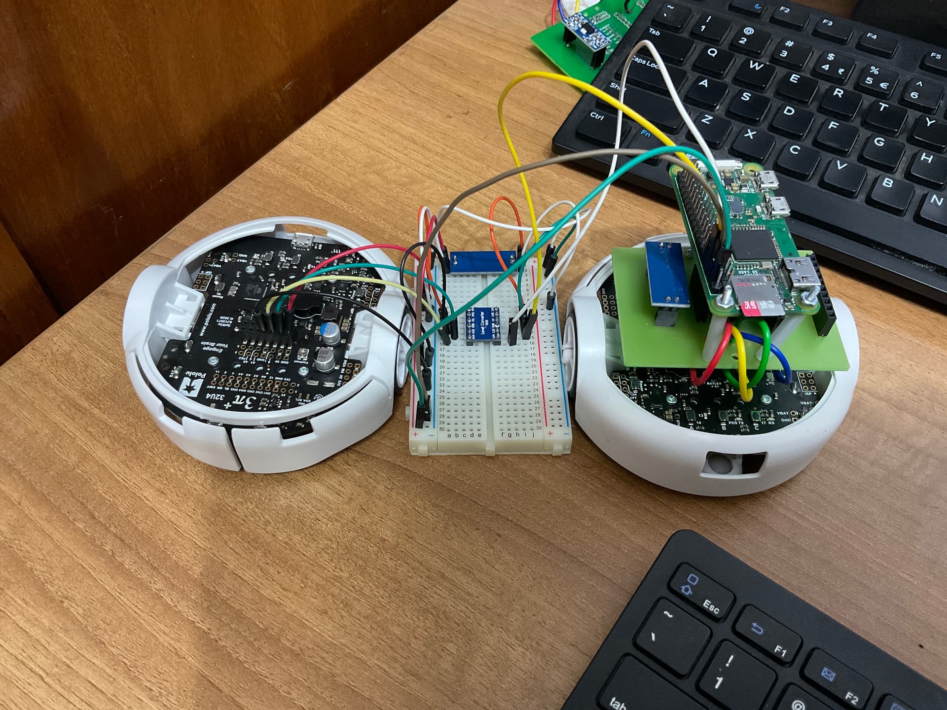
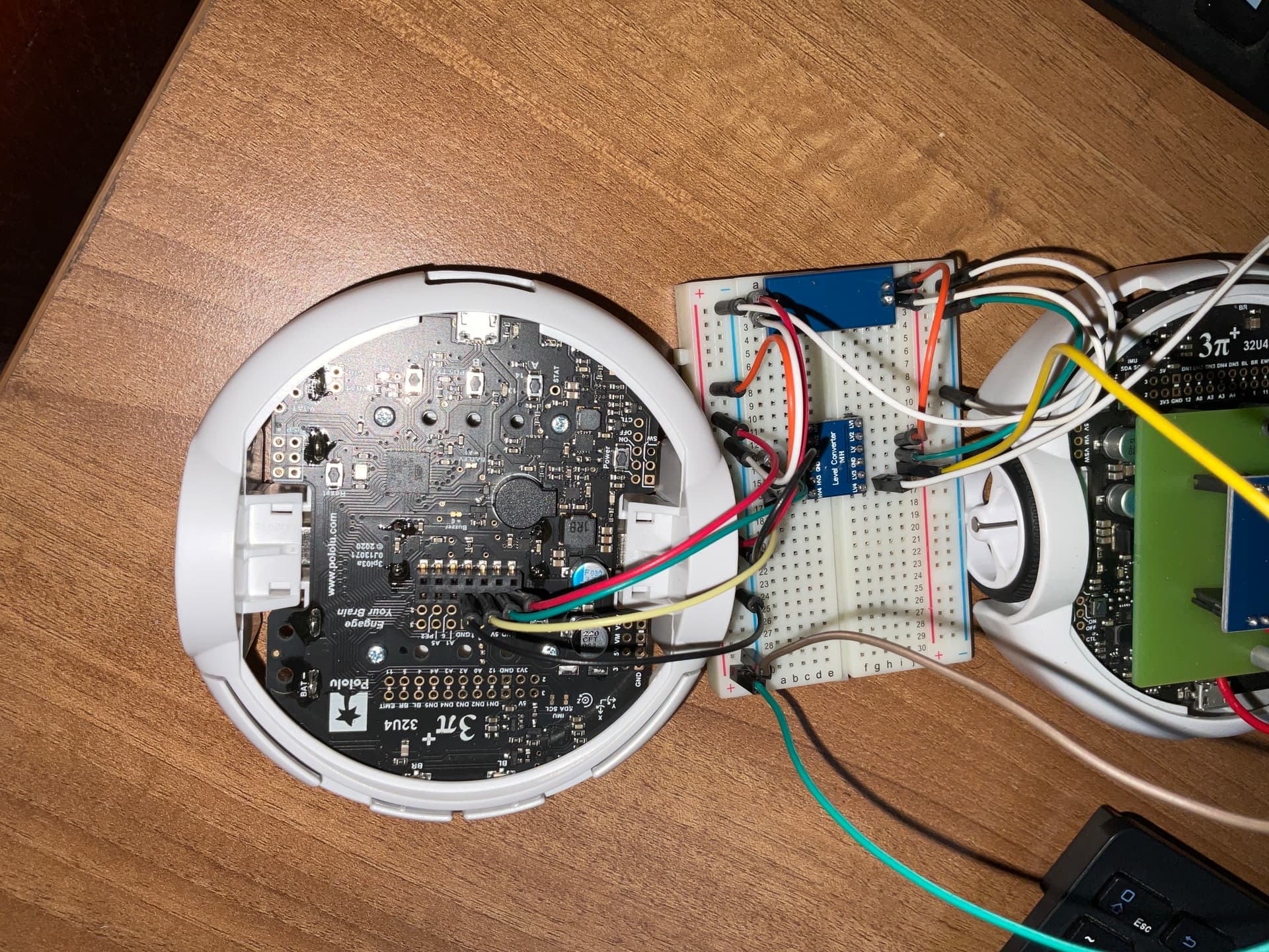
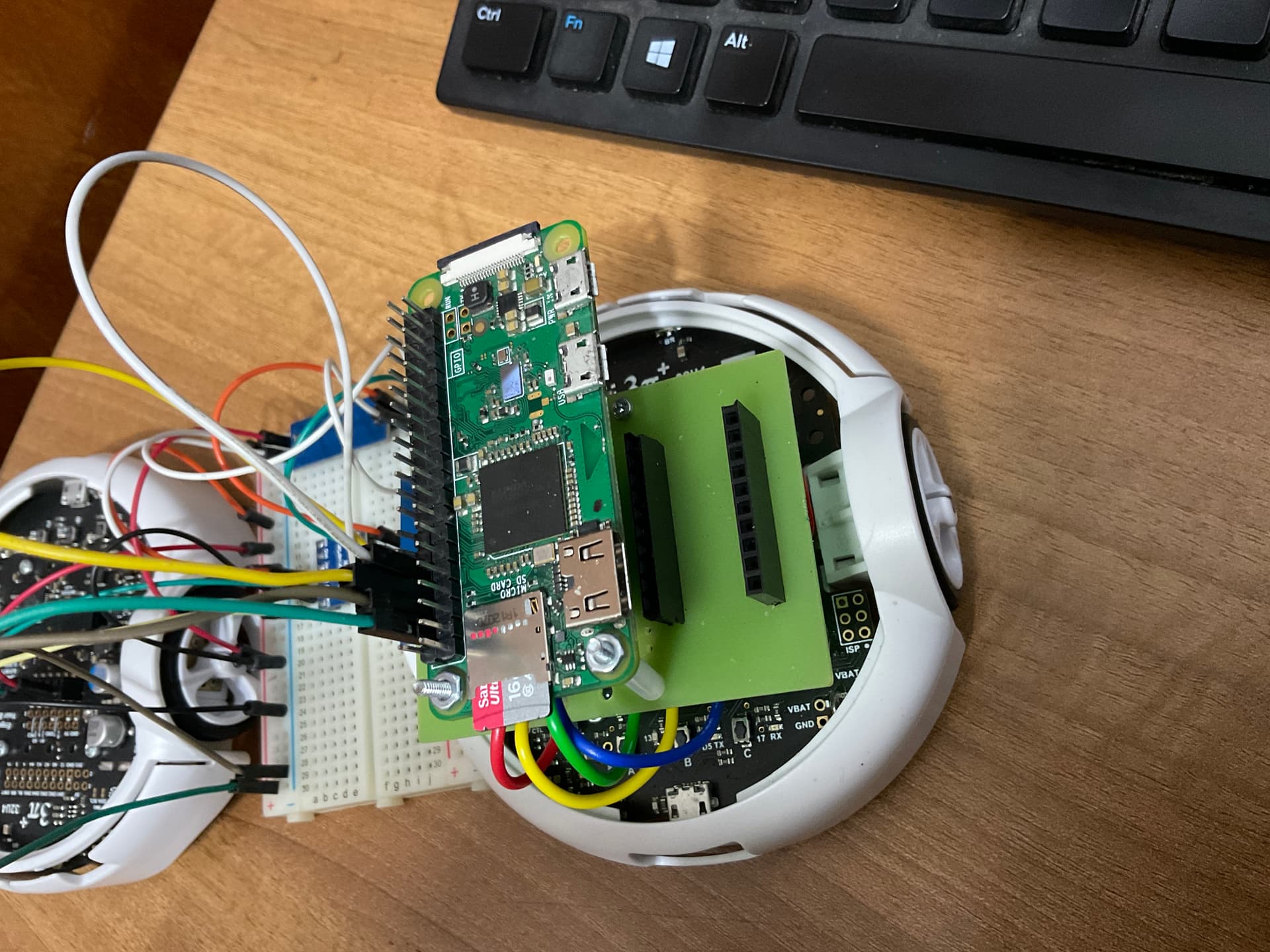
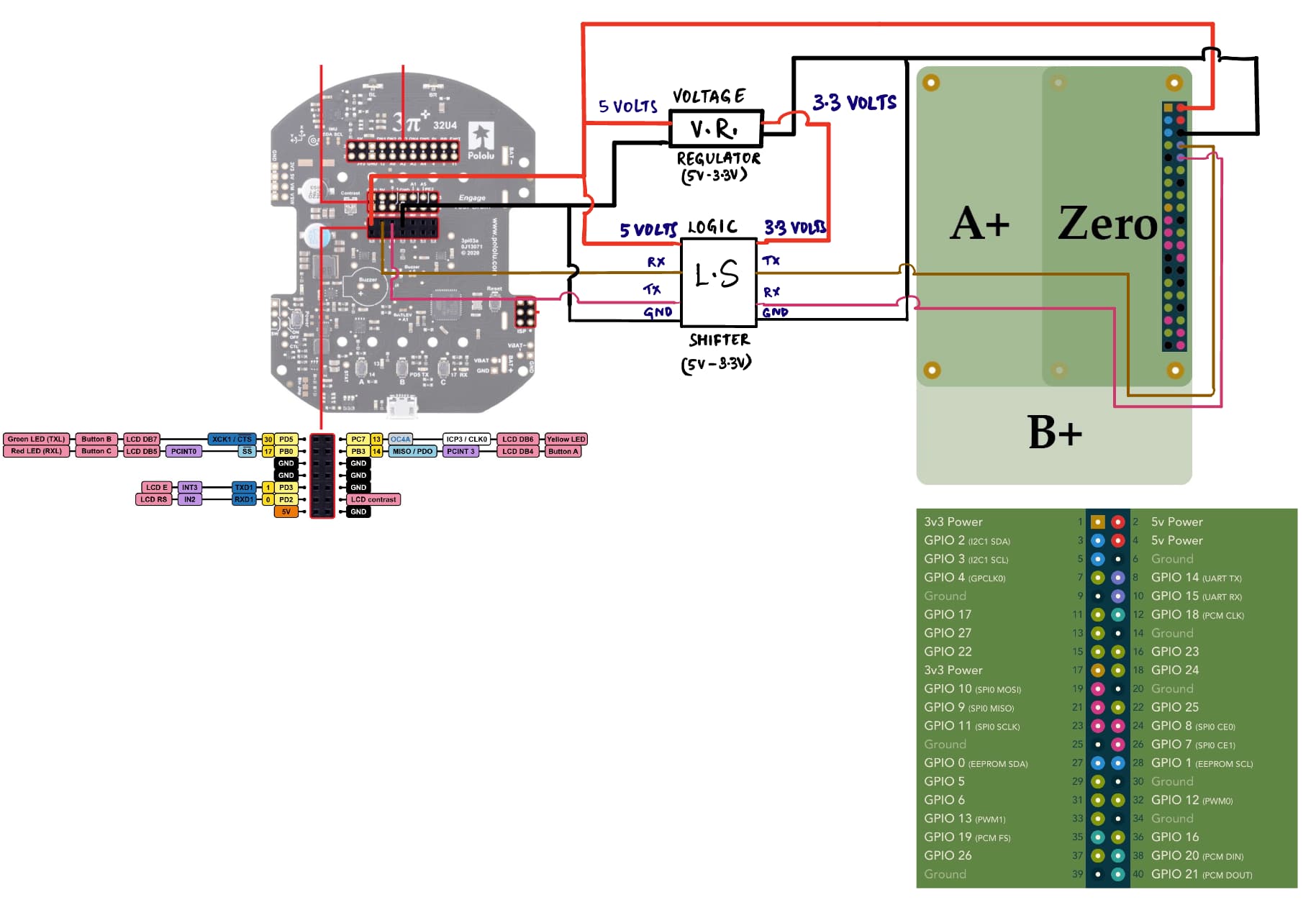
Hardware Setup
Raspberry Pi Zero
Pololu 3pi+
5V to 3.3V logic level shifter
5V to 3.3V step down voltage regulator
RASPBERRY PI PART OF CODE
Case 1- sending data from Pi to 3pi+
I have written the following code in python
import serial
import time

data = "Hello\n"

ser = serial.Serial(
    port='/dev/ttyAMA0',
    baudrate=115200,
    parity=serial.PARITY_NONE,
    stopbits=serial.STOPBITS_ONE,
    bytesize=serial.EIGHTBITS,
    timeout=1
)

while 1:
    ser.write(data.encode('utf-8'))
    time.sleep(1)
Case 2- sending data from 3pi+ to Pi
Similarly for reading from the 3pi+ (this works as intended)
import serial
import time

ser = serial.Serial(
        port='/dev/ttyAMA0',
        baudrate=115200,
        parity=serial.PARITY_NONE,
        stopbits=serial.STOPBITS_ONE,
        bytesize=serial.EIGHTBITS,
        timeout=1
)

while True:
        data = ser.readline().decode('utf-8')
        print(f"data received: {data}")
3PI+ PART OF CODE
Case 1- sending data from Pi to 3pi+
The code on 3pi+ is
#include <Pololu3piPlus32U4.h>

using namespace Pololu3piPlus32U4;

char bytes[100];

void setup() {
  // put your setup code here, to run once:
  Serial.begin(115200);
  Serial1.begin(115200);
}

void loop() {
  // put your main code here, to run repeatedly:
  Serial.print("bytes for reading: ");
  Serial.println(Serial.available());

  Serial1.readBytes(bytes,100);
  Serial1.flush();
  Serial.print("data received: "); Serial.println(bytes);
  // if (Serial1.available() > 0)
  // {
  //   // String data = Serial1.readStringUntil("\n");
  //   Serial.print("data: "); Serial.println(data);
  //   Serial1.flush();
  // }
  // delay(100);
}
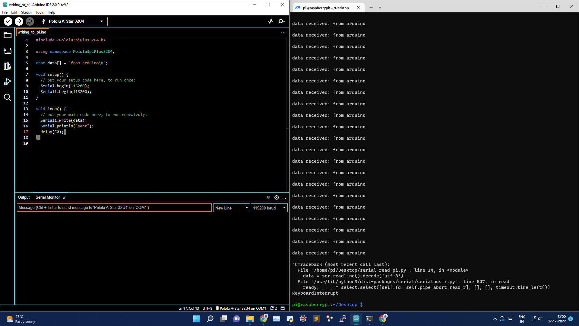
Case 2- sending data from 3pi+ to Pi
The code is as follows on the 3pi+ (works as intended)
#include <Pololu3piPlus32U4.h>

using namespace Pololu3piPlus32U4;

char data[] = "from arduino\n";

void setup() {
  // put your setup code here, to run once:
  Serial.begin(115200);
  Serial1.begin(115200);
}

void loop() {
  // put your main code here, to run repeatedly:
  Serial1.write(data);
  Serial.println("sent");
  delay(50);
}
I am not sure if I missed something trivial here or my fundamentals are shaky. Any comment is highly appreciated!
PS-
Attaching an image for Case 1

Attaching an image for Case 2
Thanks