Hello all,
I am having some issues with the I2C comms between the PIC18f452 and the Pololu 1250.
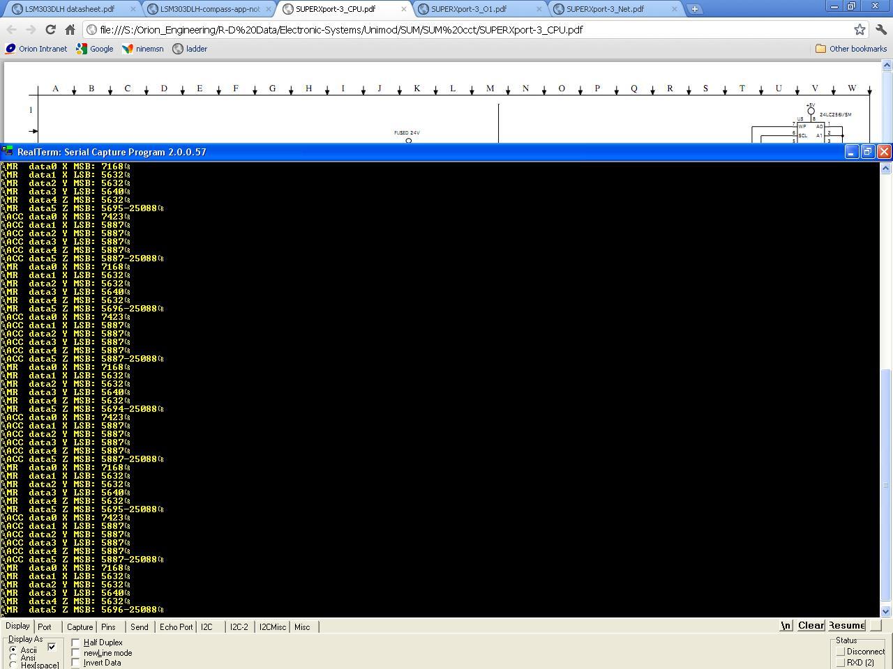
The code compiles and runs without an issue but isnt actually reading values from the sensor.
The cct is attached with relevant wires connected to Pololu board with conductivity checked to make sure all connections are good.
If anyone could point me in the rigght direction it would be appreciated.
Thankyou
#include <built_in.h>
unsigned short ACC_Data[6];
unsigned short MR_Data[5];
char st[100];
const char TX_PIN = 0;
const char RX_PIN = 1;

void initialize()
{


     PORTA = 0b00110000;
     PORTB = 0b11111111;
     PORTC = 0b00000000;
     PORTD = 0b11111111;
     PORTE = 0b00000011;

     ADCON1= 0b00000111;

     TRISA = 0x00;       // 'awake' port
     TRISB = 0x00;
     TRISC = 0b11011000; // rc6 and 7 inputs, to enable ASYNC serial COMS.
     TRISD = 0x00;       // ports B, D, A and E are outputs for the moment.
     TRISE = 0x00;       // network LEDs port


     // RE2 should be low
     // RA5 should be high
     PORTA.F5 = 1;
     PORTE.F2 = 0;

     T0CON       = 0xC4;  // Set TMR0 in 8bit mode, assign prescaler to TMR0
     TMR0L       = 96;    // Timer0 initial value
     INTCON      = 0xA0;  // Enable TMRO interrupt

     I2C_Init(100000);


     Usart_Init(9600);      //Initialise to 9600bps Baud Rate, 8 bit, no parity bit
}


void i2c_write_Accel(unsigned short accel_reg_W, unsigned short data_W)
{

///////////////////////////////////ACCELEROMETER///////////////////////////////


     //For initialise only, I2C to accelerometer
      //start setting CTRL_REG1_A register
     I2C_Start();            delay_ms(1); //send START
     I2C_Wr(0x30);           delay_ms(2); //Write device address to bus for Write mode from datasheet
     I2C_Wr(0x20);           delay_ms(2); //Write desired address bits
     I2C_Wr(0x27);           delay_ms(2); //Write device data
     I2C_Stop();             delay_ms(5); //send STOP
    //finish setting CTRL_REG1_A register

}                                //Only set 1 register from ryan TM Arduino example


void Initialise_I2C(void)
{
//Set up registers for I2C mode
SSPCON1 = 0b00101000;  //MSSP control register 1
//             | |||+---<Master mode select <0>
//             | ||+----<Master mode select <1>  //1000 is Master @ XXXMHx, 1011 is Master firmware-controlled
//             | |+-----<Master mode select <2>
//             | +------<Master mode select <3>
//             +--------<I2C enable bit (1=config pins SDA & SCL, 0=config pins as standard I/O)

SSPCON2 = 0b00000000;  //MSSP control register 2
//            ||||||+---<Start Condition Enable bit
//            |||||+----<Repeated Start Condition Enable bit
//            ||||+-----<Stop Condition Enable bit
//            |||+------<Receive Enable bit - enables Master Receive mode (1=ON, 0=OFF)
//            ||+-------<Acknowledge sequence enable bit  -Receive mode only   --|
//            |+--------<Acknowledge Data bit             -Receive mode only   --|--- work in conjunction
//            +---------<Acknowledge Status bit (1=no !ACK, 0=!ACK from slave) //Transmit mode only

SSPSTAT = 0b10000000;  //MSSP status register
//           ||     +---<Read-only, Buffer Full flag for I2C RX/TX SSPBUF 8-bit register
//           |+---------<SMBus select (1=enable, 0=disable) (high-speed I2C/SPI bus protocol)
//           +----------<Slew rate control (1=100kHz mode OFF, 0=400kHz mode ON)

SSPADD = 0b00001001;   //Set I2C baud rate @ 100kHz with 4MHz clock
//          ||     |       101000 according to datasheet, 1001 according to web example
//          |+--+--+
//          |   +-------<7-bit, (((clock/reqd_baud)/4)-1), set to 9
//          +-----------<Unused

     delay_ms(50);


     //MikroC I2C Handler Initialise
     I2C_Init(100000);
      delay_ms(50);

      delay_ms(1000);
     //Set up accelerometer
     i2c_write_Accel(0x20, 0x27);  //SET ACCELEROMETER CONTROL REG 1/3      temp removed only
     delay_ms(50);
     //Set up acelerometer
//     i2c_write_Magno(0x00, 0x14);
//     delay_ms(50);

}
void setTX()
{

   PORTC.TX_PIN = 0;


   PORTC.F5=1;
   //RxTx=1;
   Delay_ms(25);

}

void setRX() {

   Delay_ms(1);
   PORTC.TX_PIN = 1;
   PORTC.F5=0;
}


void Write_String( char *str ) {


    char c;

    setTX();

    do {
        c = *str++;
        Usart_Write(c);
    } while (c);

    setRX();


}
  void I2C_read_Accelerometer(void)
{

     I2C_Start();            delay_ms(1); //send START
     I2C_Wr(0x30);           delay_ms(2); //Write device address to bus for Write mode  ACCEL_ADDR from Arduino ex
     I2C_Wr(0x28);           delay_ms(2); //Write desired address bits                  x axis MSB
     I2C_Repeated_start();   delay_ms(1); //send repeated start
     I2C_Wr(0x31);           delay_ms(2); //Write device address to bus for Read mode   taken from MikroC I2C example
     ACC_data[0]=I2C_Rd(0);  delay_ms(1); //Read in data from register
     I2C_Stop();             delay_ms(5); //send STOP

     I2C_Start();            delay_ms(1); //send START
     I2C_Wr(0x30);           delay_ms(2); //Write device address to bus for Write mode
     I2C_Wr(0x29);           delay_ms(2); //Write desired address bits                  x axis LSB
     I2C_Repeated_start();   delay_ms(1); //send repeated start
     I2C_Wr(0x31);           delay_ms(2); //Write device address to bus for Read mode
     ACC_data[1]=I2C_Rd(0);  delay_ms(1); //Read in data from register
     I2C_Stop();             delay_ms(5); //send STOP

     I2C_Start();            delay_ms(1); //send START
     I2C_Wr(0x30);           delay_ms(2); //Write device address to bus for Write mode
     I2C_Wr(0x2A);           delay_ms(2); //Write desired address bits                  y axis MSB
     I2C_Repeated_start();   delay_ms(1); //send repeated start
     I2C_Wr(0x31);           delay_ms(2); //Write device address to bus for Read mode
     ACC_data[2]=I2C_Rd(0);  delay_ms(1); //Read in data from register
     I2C_Stop();             delay_ms(5); //send STOP

     I2C_Start();            delay_ms(1); //send START
     I2C_Wr(0x30);           delay_ms(2); //Write device address to bus for Write mode
     I2C_Wr(0x2B);           delay_ms(2); //Write desired address bits                  y axis LSB
     I2C_Repeated_start();   delay_ms(1); //send repeated start
     I2C_Wr(0x31);           delay_ms(2); //Write device address to bus for Read mode
     ACC_data[3]=I2C_Rd(0);  delay_ms(1); //Read in data from register
     I2C_Stop();             delay_ms(5); //send STOP

     I2C_Start();            delay_ms(1); //send START
     I2C_Wr(0x30);           delay_ms(2); //Write device address to bus for Write mode
     I2C_Wr(0x2C);           delay_ms(2); //Write desired address bits                  z axis MSB
     I2C_Repeated_start();   delay_ms(1); //send repeated start
     I2C_Wr(0x31);           delay_ms(2); //Write device address to bus for Read mode
     ACC_data[4]=I2C_Rd(0);  delay_ms(1); //Read in data from register
     I2C_Stop();             delay_ms(5); //send STOP

     I2C_Start();            delay_ms(1); //send START
     I2C_Wr(0x30);           delay_ms(2); //Write device address to bus for Write mode
     I2C_Wr(0x2D);           delay_ms(2); //Write desired address bits                  z axis LSB
     I2C_Repeated_start();   delay_ms(1); //send repeated start
     I2C_Wr(0x31);           delay_ms(2); //Write device address to bus for Read mode
     ACC_data[5]=I2C_Rd(0);  delay_ms(1); //Read in data from register
     I2C_Stop();             delay_ms(5); //send STOP

  }

void main()
{
initialize();
Initialise_I2C();
   while(1)
   {
   I2C_read_Accelerometer();
   sprintl( st, "ACC data0 X MSB: %i\r",ACC_data[0]);
        Write_String(st);
        sprintl( st, "ACC data1 X LSB: %i\r",ACC_data[1]);
        Write_String(st);
        sprintl( st, "ACC data2 Y MSB: %i\r",ACC_data[2]);
        Write_String(st);
        sprintl( st, "ACC data3 Y LSB: %i\r",ACC_data[3]);
        Write_String(st);
        sprintl( st, "ACC data4 Z MSB: %i\r",ACC_data[4]);
        Write_String(st);
        sprintl( st, "ACC data5 Z MSB: %i%i\r",ACC_data[5]);
        Write_String(st);
   }
}