Hi guys,
I’m trying to port the c++ code for the MinIMU9V2 into python.
Currently I’m working on the LSM303DLHC chip (Accelerometer and Magnetometer).
The aim is to get a working python version for the LSM303DLHC with automatic calibration, returning the values for magnetic X/Y/Z, acceleration X/Y/Z, the GAUSS values, the temperature and the heading.
I know the code is still a very alpha version, but this is what I’ve got so far.
Please test the code and provide helpful information in order to improve and correct the code.
#!/usr/bin/python
import smbus
import time
import math
import numpy

#initialize accelerations variables
x_data_a = 0
y_data_a = 0
z_data_a = 0

#initialize magnetics variables
x_data_m = 0
y_data_m = 0
z_data_m = 0

#set some initial values
lsb_xy_m_g                  = 1100            #as value_crb_reg_m is set to +-1.3
lsb_z_m_g                   = 980             #as value_crb_reg_m is set to +-1.3

#set the I2C ports (0x19 = accelerometer, 0x1e = magnetometer)
device_a = 0x19
device_m = 0x1E

bus=smbus.SMBus(1)

#set register values
#ctrl_reg1_a
odr_ctrl_reg1_a   = 0b0100 #50 Hz
lpen_ctrl_reg1_a  = 0b0    #low-power-mode = normal
zen_ctrl_reg1_a   = 0b1    #z axis enabled
yen_ctrl_reg1_a   = 0b1    #y axis enabled
xen_ctrl_reg1_a   = 0b1    #x axis enabled
value_ctrl_reg1_a = (odr_ctrl_reg1_a << 4) + (lpen_ctrl_reg1_a << 3) + (zen_ctrl_reg1_a << 2) + (yen_ctrl_reg1_a << 1) + xen_ctrl_reg1_a
#ctrl_reg4_a
bdu_ctrl_reg4_a   = 0b0    #continuos update
ble_ctrl_reg4_a   = 0b0    #data LSB @ lower address
fs_ctrl_reg4_a    = 0b00   #+/- 2g
hr_ctrl_reg4_a    = 0b1    #high resolution enabled
sim_ctrl_reg4_a   = 0b0    #4-wire interface
value_ctrl_reg4_a = (bdu_ctrl_reg4_a << 7) + (ble_ctrl_reg4_a << 6) + (fs_ctrl_reg4_a << 4) + (hr_ctrl_reg4_a << 3) + sim_ctrl_reg4_a
#cra_reg_m
tempen_cra_reg_m  = 0b1    #temperature sensor enabled
do_cra_reg_m      = 0b011  #7.5 minimum data output rate (Hz)
value_cra_reg_m   = (tempen_cra_reg_m << 7) + (do_cra_reg_m << 2)
#crb_reg_m
gn_crb_reg_m      = 0b001  # +-1.3 sensor input field range (Gauss), 1100 Gain X, Y and Z (LSB/Gauss) 980 Gain Z (LSB/Gauss), 0xF800-0x07ff (-2048-2047)
value_crb_reg_m   = (gn_crb_reg_m << 5)
#mr_reg_m
md_mr_reg_m       = 00     #Continuous-conversion mode
value_mr_reg_m    = md_mr_reg_m

#register address mapping accelerometer
ctrl_reg1_a       = 0x20 #rw   010 0000
ctrl_reg2_a       = 0x21 #rw   010 0001
ctrl_reg3_a       = 0x22 #rw   010 0010
ctrl_reg4_a       = 0x23 #rw   010 0011
ctrl_reg5_a       = 0x24 #rw   010 0100
ctrl_reg6_a       = 0x25 #rw   010 0101
reference_a       = 0x26 #rw   010 0110
status_reg_a      = 0x27 #r    010 0111
out_x_l_a         = 0x28 #r    010 1000
out_x_h_a         = 0x29 #r    010 1001
out_y_l_a         = 0x2A #r    010 1010
out_y_h_a         = 0x2B #r    010 1011
out_z_l_a         = 0x2C #r    010 1100
out_z_h_a         = 0x2D #r    010 1101
fifo_ctrl_reg_a   = 0x2E #rw   010 1110
fifo_src_reg_a    = 0x2F #r    010 1111
int1_cfg_a        = 0x30 #rw   011 0000
int1_source_a     = 0x31 #r    011 0001
int1_ths_a        = 0x32 #rw   011 0010
int1_duration_a   = 0x33 #rw   011 0011
int2_cfg_a        = 0x34 #rw   011 0100
int2_source_a     = 0x35 #r    011 0101
int2_ths_a        = 0x36 #rw   011 0110
int2_duration_a   = 0x37 #rw   011 0111
click_cfg_a       = 0x38 #rw   011 1000
click_src_a       = 0x39 #rw   011 1001
click_ths_a       = 0x3A #rw   011 1010
time_limit_a      = 0x3B #rw   011 1011
time_latency_a    = 0x3C #rw   011 1100
time_window_a     = 0x3D #rw   011 1101

#register address mapping magnetometer
cra_reg_m         = 0x00 #rw   00000000
crb_reg_m         = 0x01 #rw   00000001
mr_reg_m          = 0x02 #rw   00000010
out_x_h_m         = 0x03 #r    00000011
out_x_l_m         = 0x04 #r    00000100
out_z_h_m         = 0x05 #r    00000101
out_z_l_m         = 0x06 #r    00000110
out_y_h_m         = 0x07 #r    00000111
out_y_l_m         = 0x08 #r    00001000
sr_reg_mg         = 0x09 #r    00001001
ira_reg_m         = 0x0A #r    00001010
irb_reg_m         = 0x0B #r    00001011
irc_reg_m         = 0x0C #r    00001100
temp_out_h_m      = 0x31 #r    00000000
temp_out_l_m      = 0x32 #r    00000000

#Enable the Accelerometer

#power mode selection
#CTRL_REG1_A register
#ODR3 ODR2 ODR1 ODR0 LPen Zen Yen Xen
#CTRL_REG1_A description
#ODR3-0 = Data rate selection. Default value: 0 (0000: power-down, others: refer to data rate configuration
#LPen = Low-power mode enable. Default value: 0 (0: normal mode, 1: low-power mode)
#Zen = Z axis enable. Default value: 1 (0: Z axis disabled, 1: Z axis enabled)
#Yen = Y axis enable. Default value: 1 (0: Y axis disabled, 1: Y axis enabled)
#Xen = X axis enable. Default value: 1 (0: X axis disabled, 1: X axis enabled)
#rate configuration:
#0000 = Power-down mode
#0001 = Normal / low-power mode (1 Hz)
#0010 = Normal / low-power mode (10 Hz)
#0011 = Normal / low-power mode (25 Hz)
#0100 = Normal / low-power mode (50 Hz)
#0101 = Normal / low-power mode (100 Hz)
#0110 = Normal / low-power mode (200 Hz)
#0111 = Normal / low-power mode (400 Hz)
#1000 = low-power mode (1.620 Hz)
#1001 = Normal (1.344 kHz) / low-power mode (5.376 kHz)
bus.write_byte_data (device_a,ctrl_reg1_a,value_ctrl_reg1_a)
time.sleep (0.01)

#CTRL_REG4_A register
#BDU BLE FS1 FS0 HR 0(1) 0(1) SIM
#(1) This bit must be set to '0' for correct working of the device.
#CTRL_REG4_A description
#BDU = Block data update. Default value: 0 (0: continuos update, 1: output registers not updated until MSB and LSB reading
#BLE = Big/little endian data selection. Default value 0. (0: data LSB @ lower address, 1: data MSB @ lower address)
#FS1-FS0  = Full-scale selection. Default value: 00 (00: +/- 2G, 01: +/- 4G, 10: +/- 8G, 11: +/- 16G)
#HR = High resolution output mode: Default value: 0 (0: high resolution disable, 1: high resolution enable)
#SIM = SPI serial interface mode selection. Default value: 0 (0: 4-wire interface, 1: 3-wire interface).
bus.write_byte_data (device_a,ctrl_reg4_a,value_ctrl_reg4_a)
time.sleep (0.01)

#Enable the Magnetometer and Temperature sensor

#CRA_REG_M register
#TEMP_EN 0(1) 0(1) DO2 DO1 DO0 0(1) 0(1)
#(1) This bit must be set to '0' for correct working of the device
#TEMP_EN = Temperature sensor enable. 0: temperature sensor disabled (default), 1: temperature sensor enabled
#DO2 to DO0 = Data output rate bits. These bits set the rate at which data is written to all three data output registers (refer to Data rate configurations) Default value: 100
#data rate configuration:
#000 = 0.75 Minimum data output rate (Hz)
#001 = 1.5  Minimum data output rate (Hz)
#010 = 3.0  Minimum data output rate (Hz)
#011 = 7.5  Minimum data output rate (Hz)
#100 = 15   Minimum data output rate (Hz)
#101 = 30   Minimum data output rate (Hz)
#110 = 75   Minimum data output rate (Hz)
#111 = 220  Minimum data output rate (Hz)
bus.write_byte_data (device_m,cra_reg_m,value_cra_reg_m)
time.sleep (0.01)

#CRB_REG_M register
#GN2 GN1 GN0 0(1) 0(1) 0(1) 0(1) 0(1)
#(1) This bit must be set to '0' for correct working of the device
#GN1 to GN0 = Gain configuration bits. The gain configuration is common for all channels (refer to gain setting)
#gain setting:
#001 = +-1.3 sensor input field range (Gauss), 1100 Gain X, Y and Z (LSB/Gauss) 980 Gain Z (LSB/Gauss), 0xF800 - 0x07FF (-2048-2047) output range
#010 = +-1.9 sensor input field range (Gauss), 855 Gain X, Y and Z (LSB/Gauss) 760 Gain Z (LSB/Gauss), 0xF800 - 0x07FF (-2048-2047) output range
#011 = +-2.5 sensor input field range (Gauss), 670 Gain X, Y and Z (LSB/Gauss) 600 Gain Z (LSB/Gauss), 0xF800 - 0x07FF (-2048-2047) output range
#100 = +-4.0 sensor input field range (Gauss), 450 Gain X, Y and Z (LSB/Gauss) 400 Gain Z (LSB/Gauss), 0xF800 - 0x07FF (-2048-2047) output range
#101 = +-4.7 sensor input field range (Gauss), 400 Gain X, Y and Z (LSB/Gauss) 355 Gain Z (LSB/Gauss), 0xF800 - 0x07FF (-2048-2047) output range
#110 = +-5.6 sensor input field range (Gauss), 330 Gain X, Y and Z (LSB/Gauss) 295 Gain Z (LSB/Gauss), 0xF800 - 0x07FF (-2048-2047) output range
#111 = +-8.1 sensor input field range (Gauss), 230 Gain X, Y and Z (LSB/Gauss) 205 Gain Z (LSB/Gauss), 0xF800 - 0x07FF (-2048-2047) output range
bus.write_byte_data (device_m,crb_reg_m,value_crb_reg_m)
time.sleep (0.01)

#MR_REG_M register
#0(1) 0(1) 0(1) 0(1) 0(1) 0(1) MD1 MD0
#(1) This bit must be set to '0' for correct working of the device
#MD1 to MD0 = Mode select bits. These bits select the operation mode of this device (refer to magnetic sensor operation mode)
#magnetic sensor operating mode:
#00 = Continuous-conversion mode
#01 = Single-conversion mode
#10 = Sleep-mode. Device is placed in sleep-mode
#11 = Sleep-mode. Device is placed in sleep-mode
bus.write_byte_data (device_m,mr_reg_m,value_mr_reg_m)
time.sleep (0.01)

def readMagnetics(*offset):

  #read magnetics
  try:
    val_out_x_h_m = bus.read_byte_data (device_m,out_x_h_m)
    val_out_x_l_m = bus.read_byte_data (device_m,out_x_l_m)
    val_out_z_h_m = bus.read_byte_data (device_m,out_z_h_m)
    val_out_z_l_m = bus.read_byte_data (device_m,out_z_l_m)
    val_out_y_h_m = bus.read_byte_data (device_m,out_y_h_m)
    val_out_y_l_m = bus.read_byte_data (device_m,out_y_l_m)
  except IOError:
    subprocess.call(['i2cdetect', '-y', '1'])
    flag = 1     #optional flag to signal your code to resend or something

  #magnetics bite slide
  x_data_m = (((val_out_x_h_m & 0x000F) << 8) + val_out_x_l_m)
  y_data_m = (((val_out_y_h_m & 0x000F) << 8) + val_out_y_l_m)
  z_data_m = (((val_out_z_h_m & 0x000F) << 8) + val_out_z_l_m)

  #calculate two's complement
  x_data_m = twos_comp(x_data_m, 12)
  y_data_m = twos_comp(y_data_m, 12)
  z_data_m = twos_comp(z_data_m, 12)

  #remove the noise
  x_data_m = x_data_m - offset[0]
  y_data_m = y_data_m - offset[1]
  z_data_m = z_data_m - offset[2]

  return [(x_data_m),(y_data_m),(z_data_m)]

def readMagneticGauss(*offset):

  global lsb_xy_m_g
  global lsb_z_m_g

  mag_factor = 1 / float(lsb_xy_m_g) #magnetic factor

  #get the magnetic values
  magnetics = readMagnetics(*offset)
  x_data_m = magnetics[0]
  y_data_m = magnetics[1]
  z_data_m = magnetics[2]

  #adjust the magnetic gain value
  if (x_data_m >= 4090 or x_data_m <= -4090 or y_data_m >= 4090 or y_data_m <= -4090 or z_data_m >= 4090 or z_data_m <= -4090):
    magneticGain = setMagneticGain(gn_crb_reg_m)
    lsb_xy_m_g = magneticGain[0]
    lsb_z_m_g = magneticGain[1]
    mag_factor = magneticGain[2]

  #calculate magnetic Gauss unit
  x_data_m_g = x_data_m * mag_factor
  y_data_m_g = y_data_m * mag_factor
  z_data_m_g = z_data_m * mag_factor

  return [(x_data_m_g),(y_data_m_g),(z_data_m_g)]

def readMagneticHeading(*offset):

  #get the magnetic gauss values
  magnetic_gauss = readMagneticGauss(*offset)
  x_data_m_g = magnetic_gauss[0]
  y_data_m_g = magnetic_gauss[1]

  #calculate the heading
  heading_d_m = math.degrees(math.atan2(y_data_m_g, x_data_m_g))
  heading_wd_m = ''

  if (heading_d_m < 0):
    heading_d_m += 360

  #get the wind direction
  if (heading_d_m > 337.5 or heading_d_m <= 22.5):
    heading_wd_m = 'N'
  elif (heading_d_m > 22.5 and heading_d_m <= 67.5):
    heading_wd_m = 'NE'
  elif (heading_d_m > 67.5 and heading_d_m <= 110.5):
    heading_wd_m = 'E'
  elif (heading_d_m > 110.5 and heading_d_m <= 157.5):
    heading_wd_m = 'SE'
  elif (heading_d_m > 157.5 and heading_d_m <= 202.5):
    heading_wd_m = 'S'
  elif (heading_d_m > 202.5 and heading_d_m <= 247.5):
    heading_wd_m = 'SW'
  elif (heading_d_m > 247.5 and heading_d_m <= 292.5):
    heading_wd_m = 'W'
  elif (heading_d_m > 292.5 and heading_d_m <= 337.5):
    heading_wd_m = 'NW'
  else:
    heading_wd_m = heading_d_m

  return [(heading_d_m), (heading_wd_m)]

def readTemperatures():

  temp_data_m_c_offset = 19.5

  #read temperature
  val_temp_out_l_m = bus.read_byte_data (device_m, temp_out_l_m)
  val_temp_out_h_m = bus.read_byte_data (device_m, temp_out_h_m)

  #temperature bite slide
  temp_data_m = (((val_temp_out_h_m << 8) + val_temp_out_l_m) >> 4) #temperature raw
  temp_data_m_c = (twos_comp(temp_data_m, 12) / 8.0) + temp_data_m_c_offset #temperature in celsuis + offset
  temp_data_m_f = temp_data_m_c * 1.8 + 32 #temperature in fahrenheit

  return [(temp_data_m_c),(temp_data_m_f)]

def readAccelerations():

  #read accelerations
  try:
    val_out_x_l_a = bus.read_byte_data (device_a,out_x_l_a)
    val_out_x_h_a = bus.read_byte_data (device_a,out_x_h_a)
    val_out_y_l_a = bus.read_byte_data (device_a,out_y_l_a)
    val_out_y_h_a = bus.read_byte_data (device_a,out_y_h_a)
    val_out_z_l_a = bus.read_byte_data (device_a,out_z_l_a)
    val_out_z_h_a = bus.read_byte_data (device_a,out_z_h_a)
  except IOError:
    subprocess.call(['i2cdetect', '-y', '1'])
    flag = 1     #optional flag to signal your code to resend or something

  #accelerations bite slide
  x_data_a = (((val_out_x_h_a << 8) + val_out_x_l_a) >> 4)
  y_data_a = (((val_out_y_h_a << 8) + val_out_y_l_a) >> 4)
  z_data_a = (((val_out_z_h_a << 8) + val_out_z_l_a) >> 4)

  #calculate two's complement
  x_data_a = twos_comp(x_data_a, 12)
  y_data_a = twos_comp(y_data_a, 12)
  z_data_a = twos_comp(z_data_a, 12)

  return [(x_data_a),(y_data_a),(z_data_a)]

def readAccelerationG():

  #get the acceleration values
  accelerations = readAccelerations()
  x_data_a = accelerations[0]
  y_data_a = accelerations[1]
  z_data_a = accelerations[2]

  accelFactor = setAccelerationScale(fs_ctrl_reg4_a)

  #calc accelerations in G unit
  x_data_a_g = x_data_a * accelFactor
  y_data_a_g = y_data_a * accelFactor
  z_data_a_g = z_data_a * accelFactor

  return [(x_data_a_g),(y_data_a_g),(z_data_a_g)]

def setAccelerationScale(scale):
  if scale == 0b00: #+/- 2G
    accelFactor = 0.001
  elif scale == 0b01: #+/- 4G
    accelFactor = 0.002
  elif scale == 0b10: #+/- 8G
    accelFactor = 0.004
  elif scale == 0b11: #+/- 16G
    accelFactor = 0.012

  return accelFactor

def setMagneticGain(gain):

  test1 = bus.read_byte_data (device_m,crb_reg_m,value_crb_reg_m)
  print "Test1: " % test1

  if gain == 0b001: #+-1.3
    lsb_xy_m_g = 855
    lsb_z_m_g = 760
    gn_crb_reg_m = 0b010
    print "Changing range to +/- 1.9"
  elif gain == 0b010: #+-1.9
    lsb_xy_m_g = 670
    lsb_z_m_g = 600
    gn_crb_reg_m = 0b011
    print "Changing range to +/- 2.5"
  elif gain == 0b011: #+-2.5
    lsb_xy_m_g = 450
    lsb_z_m_g = 400
    gn_crb_reg_m = 0b100
    print "Changing range to +/- 4.0"
  elif gain == 0b100: #+-4.0
    lsb_xy_m_g = 400
    lsb_z_m_g = 255
    gn_crb_reg_m = 0b101
    print "Changing range to +/- 4.7"
  elif gain == 0b101: #+-4.7
    lsb_xy_m_g = 330
    lsb_z_m_g = 295
    gn_crb_reg_m = 0b110
    print "Changing range to +/- 5.6"
  elif gain == 0b110: #+-5.6
    lsb_xy_m_g = 230
    lsb_z_m_g = 205
    gn_crb_reg_m = 0b111
    print "Changing range to +/- 8.1"
  elif gain == 0b111: #+-8.1
    lsb_xy_m_g = 230
    lsb_z_m_g = 205
    gn_crb_reg_m = 0b111
    print "Remaining at +/- 8.1"

  mag_factor = 1 / lsb_xy_m_g

  value_crb_reg_m   = (gn_crb_reg_m << 5)
  bus.write_byte_data (device_m,crb_reg_m,value_crb_reg_m)

  print "bus written..."

  test2 = bus.read_byte_data (device_m,crb_reg_m,value_crb_reg_m)
  print "Test2: %s" % test2

  time.sleep (0.01)

  return [(lsb_xy_m_g), (lsb_z_m_g), (mag_factor)]

def twos_comp(val, bits):

  #compute the 2's compliment of int value val
  if((val&(1<<(bits-1))) != 0):
    val = val - (1<<bits)

  return val

def calibrateMag():

  print "Calibrating Magnetometer, please move sensor to all directions..."
  time.sleep(15) #delay for 15 seconds
  print "Start moving now..."

  x_min_m = 999999
  y_min_m = 999999
  z_min_m = 999999
  x_max_m = -999999
  y_max_m = -999999
  z_max_m = -999999

  for i in range (1,1000):

    x_value_m = readMagnetics(0,0,0)[0]
    y_value_m = readMagnetics(0,0,0)[1]
    z_value_m = readMagnetics(0,0,0)[2]

    if(x_value_m < x_min_m):
      x_min_m = x_value_m
    elif(x_value_m > x_max_m):
      x_max_m = x_value_m

    if(y_value_m < y_min_m):
      y_min_m = y_value_m
    elif(y_value_m > y_max_m):
      y_max_m = y_value_m

    if(z_value_m < z_min_m):
      z_min_m = z_value_m
    elif(z_value_m > z_max_m):
      z_max_m = z_value_m

  x_offset_m = (x_min_m + x_max_m) / 2
  y_offset_m = (y_min_m + y_max_m) / 2
  z_offset_m = (z_min_m + z_max_m) / 2

  print "Magnetometer minimum values are: {0}, {1}, {2}".format(x_min_m, y_min_m, z_min_m)
  print "Magnetometer maximum values are: {0}, {1}, {2}".format(x_max_m, y_max_m, z_max_m)
  print "Magnetometer average values are: {0}, {1}, {2}".format(x_offset_m, y_offset_m, z_offset_m)

return [(x_offset_m),(y_offset_m),(z_offset_m)]#!/usr/bin/python
import LSM303DLHC
import L3GD20
import time
import sys
#calibrate the Gyrometer
xyz_offset_g = L3GD20.calibrateGyro()
#calibrate the Magnetometer
xyz_offset_m = LSM303DLHC.calibrateMag()
print "XYZ_OFFSET_G: {0}".format(xyz_offset_g)
print "XYZ_OFFSET_M: {0}".format(xyz_offset_m)
while 1:
magneticsRaw = LSM303DLHC.readMagnetics(*xyz_offset_m)
magneticGauss = LSM303DLHC.readMagneticGauss(*xyz_offset_m)
magneticHeading = LSM303DLHC.readMagneticHeading(*xyz_offset_m)
magneticTemp = LSM303DLHC.readTemperatures()
accelerationsRaw = LSM303DLHC.readAccelerations()
accelerationG = LSM303DLHC.readAccelerationG()
gyroRaw = L3GD20.readGyro(*xyz_offset_g)
gyroDPS = L3GD20.readDPS(*xyz_offset_g)
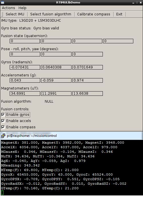
print "MagnetX: {0}, MagnetY: {1}, MagnetZ: {2}".format(magneticsRaw[0], magneticsRaw[1], magneticsRaw[2])
print "AccelX: {0}, AccelY: {1}, AccelZ: {2}".format(accelerationsRaw[0], accelerationsRaw[1], accelerationsRaw[2])
print "MGaussX: {0}, MGaussY: {1}, MGaussZ: {2}".format(magneticGauss[0], magneticGauss[1], magneticGauss[2])
print "MuTX: {0}, MuTY: {1}, MuTZ: {2}".format(magneticGauss[0] * 100, magneticGauss[1] * 100, magneticGauss[2] * 100)
print "AgX: {0}, AgY: {1}, AgZ: {2}".format(accelerationG[0], accelerationG[1], accelerationG[2])
print "MHeading: {0}".format(magneticHeading[0])
print "MWindDir: {0}".format(magneticHeading[1])
print "MTemp(F): {0}, MTemp(C): {1}".format(magneticTemp[0], magneticTemp[1])
print "GyroX: {0}, GyroY: {1}, GyroZ: {2}".format(gyroRaw[0], gyroRaw[1], gyroRaw[2])
print "GyroDPSX: {0}, GyroDPSY: {1}, GyroDPSZ: {2}".format(gyroDPS[0], gyroDPS[1], gyroDPS[2])
sys.stdout.flush()
time.sleep(0.1)#!/usr/bin/python
import smbus
import time
#initialize gyro variables
x_data_g = 0
y_data_g = 0
z_data_g = 0
#set the I2C ports (0x6b = gyrometer)
device_g = 0x6b
bus=smbus.SMBus(1)
#set register values
#ctrl_reg1_g
dr_ctrl_reg1_g = 0b00 #ODR 95 Hz
bw_ctrl_reg1_g = 0b00 #Cut-Off 12.5
pd_ctrl_reg1_g = 0b0 #power-down mode
zen_ctrl_reg1_g = 0b1 #z axis enabled
xen_ctrl_reg1_g = 0b1 #x axis enabled
yen_ctrl_reg1_g = 0b1 #y axis enabled
value_ctrl_reg1_g = (dr_ctrl_reg1_g << 6) + (bw_ctrl_reg1_g << 4) + (pd_ctrl_reg1_g << 3) + (zen_ctrl_reg1_g << 2) + (xen_ctrl_reg1_g << 1) + yen_ctrl_reg1_g
#ctrl_reg2_g
hpm_ctrl_reg2_g = 0b00 #High pass filter mode normal
hpc_ctrl_reg2_g = 0b0000 #ODR 95Hz / cut-off 7.2, ODR 190Hz / cut-off 13.5, ODR 380Hz / cut-off 27, ODR 760Hz / cut-off 51.4
value_ctrl_reg2_g = (hpm_ctrl_reg2_g << 4) + hpc_ctrl_reg2_g
#ctrl_reg3_g
i1_ctrl_reg3_g = 0b00 #Interrupt disable on INT1 pin, Boot status available on INT1 disabled
h_ctrl_reg3_g = 0b0 #Interrupt active configuration on INT1 high
pp_ctrl_reg3_g = 0b0 #push-pull
i2_ctrl_reg3_g = 0b0000 #Date-ready on DRDYANT2 disabled, FIFO watermarking interrupt on DRDYANT2 disabled, FIFO overrun interrupt on DRDYANT2 disabled, FIFO empty interrupt on DRDYANT2 disabled
value_ctrl_reg3_g = (i1_ctrl_reg3_g << 6) + (h_ctrl_reg3_g << 5) + (pp_ctrl_reg3_g << 4) + i2_ctrl_reg3_g
#ctrl_reg4_g
bdu_ctrl_reg4_g = 0b0 #Block data update continuos
ble_ctrl_reg4_g = 0b0 #Big/little endian data selection data lsb @ low address
fs_ctrl_reg4_g = 0b00 #full scale selection 250 dps
sim_ctrl_reg4_g = 0b0 #SPI serial interface mode selection 4-wire interface
value_ctrl_reg4_g = (bdu_ctrl_reg4_g << 7) + (ble_ctrl_reg4_g << 6) + (fs_ctrl_reg4_g << 4) + sim_ctrl_reg4_g
#ctrl_reg5_g
boot_ctrl_reg5_g = 0b0 #Reboot memory content normal mode
fifo_ctrl_reg5_g = 0b0 #FIFO disabled
hpen_ctrl_reg5_g = 0b0 #High-pass filter disabled
int1_ctrl_reg5_g = 0b00 #INT1 selection configuration wait disabled
out_ctrl_reg5_g = 0b00 #OUT selection configuration wait disabled
value_ctrl_reg5_g = (boot_ctrl_reg5_g << 7) + (fifo_ctrl_reg5_g << 6) + (hpen_ctrl_reg5_g << 4) + (int1_ctrl_reg5_g << 2) + out_ctrl_reg5_g
who_am_i_g = 0x0f #r 0001111 Device identification register
ctrl_reg1_g = 0x20 #rw 0100000 Control register 1
ctrl_reg2_g = 0x21 #rw 0100001 Control register 2
ctrl_reg3_g = 0x22 #rw 0100010 Control register 3
ctrl_reg4_g = 0x23 #rw 0100011 Control register 4
ctrl_reg5_g = 0x24 #rw 0100100 Control register 5
reference_g = 0x25 #rw 0100101 Reference value for interrupt generation
out_temp_g = 0x26 #r 0100110 Output temperature
status_reg_g = 0x27 #r 0100111 Status register
out_x_l_g = 0x28 #r 0101000 X-axis angular data rate LSB
out_x_h_g = 0x29 #r 0101001 X-axis angular data rate MSB
out_y_l_g = 0x2a #r 0101010 Y-axis angular data rate LSB
out_y_h_g = 0x2b #r 0101011 Y-axis angular data rate MSB
out_z_l_g = 0x2c #r 0101100 Z-axis angular data rate LSB
out_z_h_g = 0x2d #r 0101101 Z-axis angular data rate MSB
fifo_ctrl_reg_g = 0x2e #rw 0101110 Fifo control register
fifo_src_reg_g = 0x2f #r 0101111 Fifo src register
int1_cfg_g = 0x30 #rw 0110000 Interrupt 1 configuration register
int1_src_g = 0x31 #r 0110001 Interrupt source register
int1_ths_xh_g = 0x32 #rw 0110010 Interrupt 1 threshold level X MSB register
int1_ths_xl_g = 0x33 #rw 0110011 Interrupt 1 threshold level X LSB register
int1_ths_yh_g = 0x34 #rw 0110100 Interrupt 1 threshold level Y MSB register
int1_ths_yl_g = 0x35 #rw 0110101 Interrupt 1 threshold level Y LSB register
int1_ths_zh_g = 0x36 #rw 0110110 Interrupt 1 threshold level Z MSB register
int1_ths_zl_g = 0x37 #rw 0110111 Interrupt 1 threshold level Z LSB register
int1_duration_g = 0x38 #rw 0111000 Interrupt 1 duration register
#Enable the Gyrometer
#CTRL_REG1_G register
#DR1 DR0 BW1 BW0 PD Zen Xen Yen
#CTRL_REG1_G description
#DR1-DR0 = Output data rate selection (refer to DR and BW configuration setting)
#BW1-BW0 = Bandwidth selection (refer to DR and BW configuration setting)
#PD = Power-down mode enable. Devault value: 0 (0: power-down mode, 1: normal mode or sleep mode) (refer to power mode selection configuration)
#Zen = Z axis enable, Default value: 1 (0: Z axis disabled, 1: Z axis enabled)
#Yen = Y axis enable, Default value: 1 (0: Y axis disabled, 1: Y axis enabled)
#Xen = X axis enable, Default value: 1 (0: X axis disabled, 1: X axis enabled)
#DR and BW configuration setting:
#0000 = ODR 95 Hz, Cut-Off 12.5
#0001 = ODR 95 Hz, Cut-Off 25
#0010 = ODR 95 Hz, Cut-Off 25
#0011 = ODR 95 Hz, Cut-Off 25
#0100 = ODR 190 Hz, Cut-Off 12.5
#0101 = ODR 190 Hz, Cut-Off 25
#0110 = ODR 190 Hz, Cut-Off 50
#0111 = ODR 190 Hz, Cut-Off 70
#1000 = ODR 380 Hz, Cut-Off 20
#1001 = ODR 380 Hz, Cut-Off 25
#1010 = ODR 380 Hz, Cut-Off 50
#1011 = ODR 380 Hz, Cut-Off 100
#1100 = ODR 760 Hz, Cut-Off 30
#1101 = ODR 760 Hz, Cut-Off 35
#1110 = ODR 760 Hz, Cut-Off 50
#1111 = ODR 760 Hz, Cut-Off 100
#power mode selection configuration:
#PD Zen Yen Xen Mode
#0 - - - power-down
#1 0 0 0 sleep
#1 - - - normal
bus.write_byte_data (device_g,ctrl_reg1_g,value_ctrl_reg1_g)
time.sleep (0.01)
#CTRL_REG2_G register
#0(1) 0(1) HPM1 HPM0 HPCF3 HPCF2 HPCF1 HPCF0
#(1) These bits must be set to '0' to ensure proper operation of the device
#CTRL_REG2_G description
#HPM1-HPM0 = High-pass filter mode selection. Default value: 00 (refer to high-pass filter mode configuration)
#HPCF3-HPCF0 = High-pass filter cutoff frequency selection (refer to high-pass filter cut off frequency configuration (Hz)
#high-pass filter mode configuration
#HPM1 HPM0 High-pass filter mode
#0 0 Normal mode (reset reading HP_RESET_FILTER)
#0 1 Reference signal for filtering
#1 0 Normal mode
#1 1 Autoreset on interrupt event
#high-pass filter cut off frequency configuration
#HPCF3-0 ODR=95 Hz ODR=190 Hz ODR=380 Hz ODR=760 Hz
#0000 7.2 13.5 27 51.4
#0001 3.5 7.2 13.5 27
#0010 1.8 3.5 7.2 13.5
#0011 0.9 1.8 3.5 7.2
#0100 0.45 0.9 1.8 3.5
#0101 0.18 0.45 0.9 1.8
#0110 0.09 0.18 0.45 0.9
#0111 0.045 0.09 0.18 0.45
#1000 0.018 0.045 0.09 0.18
#1001 0.009 0.018 0.045 0.09
bus.write_byte_data (device_g,ctrl_reg2_g,value_ctrl_reg2_g)
time.sleep (0.01)
#CTRL_REG3_G register
#I1_Int1 I1_Boot H_Lactive PP_OD I2_DRDY I2_WTM I2_ORun I2_Empty
#CTRL_REG3_G description
#I1_Int1 = Interrupt enable on INT1 pin. Default value 0. (0: disable; 1: enable)
#I1_Boot = Boot status available on INT1. Default value 0. (0: disable; 1: enable)
#H_Lactive = Interrupt active configuration on INT1. Default value 0. (0: high; 1:low)
#PP_OD = Push-pull / Open drain. Default value: 0. (0: push- pull; 1: open drain)
#I2_DRDY = Date-ready on DRDY/INT2. Default value 0. (0: disable; 1: enable)
#I2_WTM = FIFO watermark interrupt on DRDY/INT2. Default value: 0. (0: disable; 1: enable)
#I2_ORun = FIFO overrun interrupt on DRDY/INT2 Default value: 0. (0: disable; 1: enable)
#I2_Empty = FIFO empty interrupt on DRDY/INT2. Default value: 0. (0: disable; 1: enable)
bus.write_byte_data (device_g,ctrl_reg3_g,value_ctrl_reg3_g)
time.sleep (0.01)
#CTRL_REG4_G register
#BDU BLE FS1 FS0 - 0(1) 0(1) SIM
#(1) This value must not be changed.
#CTRL_REG4_G description
#BDU = Block data update. Default value: 0 (0: continuos update; 1: output registers not updated until MSb and LSb read-ing)
#BLE = Big/little endian data selection. Default value 0.(0: Data LSb @ lower address; 1: Data MSb @ lower address)
#FS1-FS0 = Full scale selection. Default value: 00 (00: 250 dps; 01: 500 dps; 10: 2000 dps; 11: 2000 dps)
#SIM = SPI serial interface mode selection. Default value: 0 (0: 4-wire interface; 1: 3-wire interface).
bus.write_byte_data (device_g,ctrl_reg4_g,value_ctrl_reg4_g)
time.sleep (0.01)
#CTRL_REG5_G register
#BOOT FIFO_EN - HPen INT1_Sel1 INT1_Sel0 Out_Sel1 Out_Sel0
#CTRL_REG5_G description
#BOOT = Reboot memory content. Default value: 0 (0: normal mode; 1: reboot memory content)
#FIFO_EN = FIFO enable. Default value: 0 (0: FIFO disable; 1: FIFO Enable)
#HPen = High-pass filter enable. Default value: 0 (0: HPF disabled; 1: HPF enabled See Figure 20)
#INT1_Sel1-INT1_-Sel0 = INT1 selection configuration. Default value: 0 (0: wait disabled, 1: wait enabled)
#Out_Sel1-Out_-Sel1 = Out selection configuration. Default value: 0 (0: wait disabled, 1: wait enabled)
bus.write_byte_data (device_g,ctrl_reg5_g,value_ctrl_reg5_g)
time.sleep (0.01)
def readGyro(*offset):
#read gyro values
try:
val_out_x_h_g = bus.read_byte_data (device_g,out_x_h_g)
val_out_x_l_g = bus.read_byte_data (device_g,out_x_l_g)
val_out_z_h_g = bus.read_byte_data (device_g,out_z_h_g)
val_out_z_l_g = bus.read_byte_data (device_g,out_z_l_g)
val_out_y_h_g = bus.read_byte_data (device_g,out_y_h_g)
val_out_y_l_g = bus.read_byte_data (device_g,out_y_l_g)
except IOError:
subprocess.call(['i2cdetect', '-y', '1'])
flag = 1 #optional flag to signal your code to resend or something
#gyro bite slide
x_data_g = ((val_out_x_h_g << 8) + val_out_x_l_g)
y_data_g = ((val_out_y_h_g << 8) + val_out_y_l_g)
z_data_g = ((val_out_z_h_g << 8) + val_out_z_l_g)
#calculate two's complement
y_data_g = twos_comp(x_data_g, 16)
y_data_g = twos_comp(y_data_g, 16)
z_data_g = twos_comp(z_data_g, 16)
#remove the noise
x_data_g = x_data_g - offset[0]
y_data_g = y_data_g - offset[1]
z_data_g = z_data_g - offset[2]
return [(x_data_g),(y_data_g),(z_data_g)]
def readDPS(*offset):
#read the gyro values
xyz_data_g = readGyro(*offset)
gyroFactor = setGyroScale(fs_ctrl_reg4_g)
#convert values into degrees per second
value_dps_x_g = xyz_data_g[0] * gyroFactor
value_dps_y_g = xyz_data_g[1] * gyroFactor
value_dps_z_g = xyz_data_g[2] * gyroFactor
return [(value_dps_x_g),(value_dps_y_g),(value_dps_z_g)]
def setGyroScale(scale):
if scale == 0b00: #250 dps
gyroFactor = 0.00875
elif scale == 0b01: #500 dps
gyroFactor = 0.01750
elif scale == 0b10: #2000 dps
gyroFactor = 0.070
return gyroFactor
def twos_comp(val, bits):
#compute the 2's compliment of int value val
if((val&(1<<(bits-1))) != 0):
val = val - (1<<bits)
return val
def calibrateGyro():

  x_value_g = 0
  y_value_g = 0
  z_value_g = 0
  x_offset_g = 0
  y_offset_g = 0
  z_offset_g = 0

  print "Calibrating Gyrometer, please do not move sensor..."
  time.sleep(15) #delay for 15 seconds

  for i in range (1,1000):

    #read the gyro values
    x_value_g = readGyro(0,0,0)[0]
    y_value_g = readGyro(0,0,0)[1]
    z_value_g = readGyro(0,0,0)[2]

    #sum up the readings
    x_offset_g += x_value_g
    y_offset_g += y_value_g
    z_offset_g += z_value_g

  #average the readings
  x_offset_g = x_offset_g / 1000
  y_offset_g = y_offset_g / 1000
  z_offset_g = z_offset_g / 1000

  print "Gyrometer offset values are: '{0}', '{1}', '{2}'".format(x_offset_g, y_offset_g, z_offset_g)

return [(x_offset_g),(y_offset_g),(z_offset_g)]Thanks!
updated 26.08.2014