Can I paste my code or email it to someone to look at it? All my robot will do is turn left because well only the right track works. You can email me if that helps. I have never used a forum before.
Nicholas Victoria
Can I paste my code or email it to someone to look at it? All my robot will do is turn left because well only the right track works. You can email me if that helps. I have never used a forum before.
Nicholas Victoria
Hello, Nicholas.
You can post your code here.
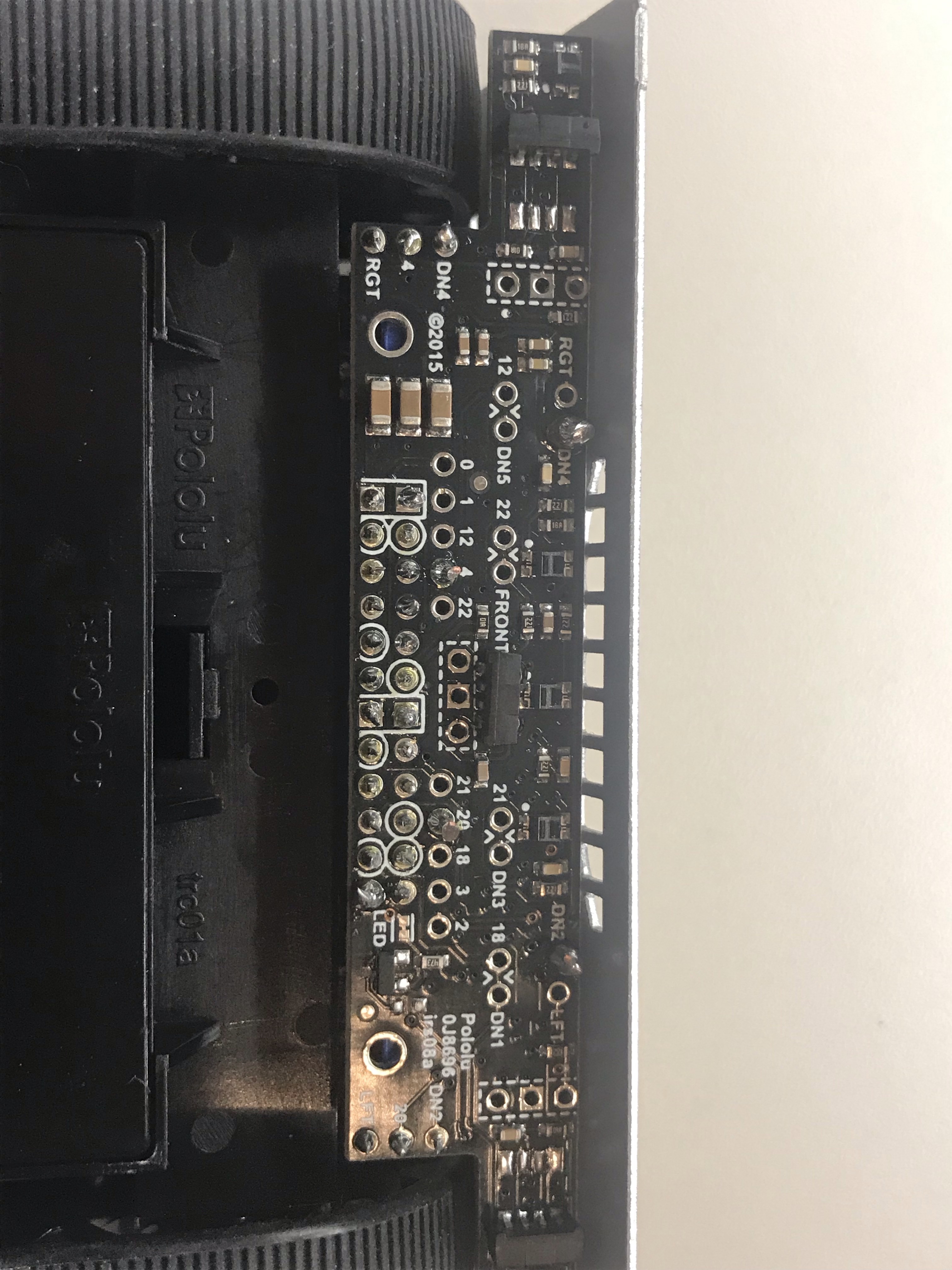
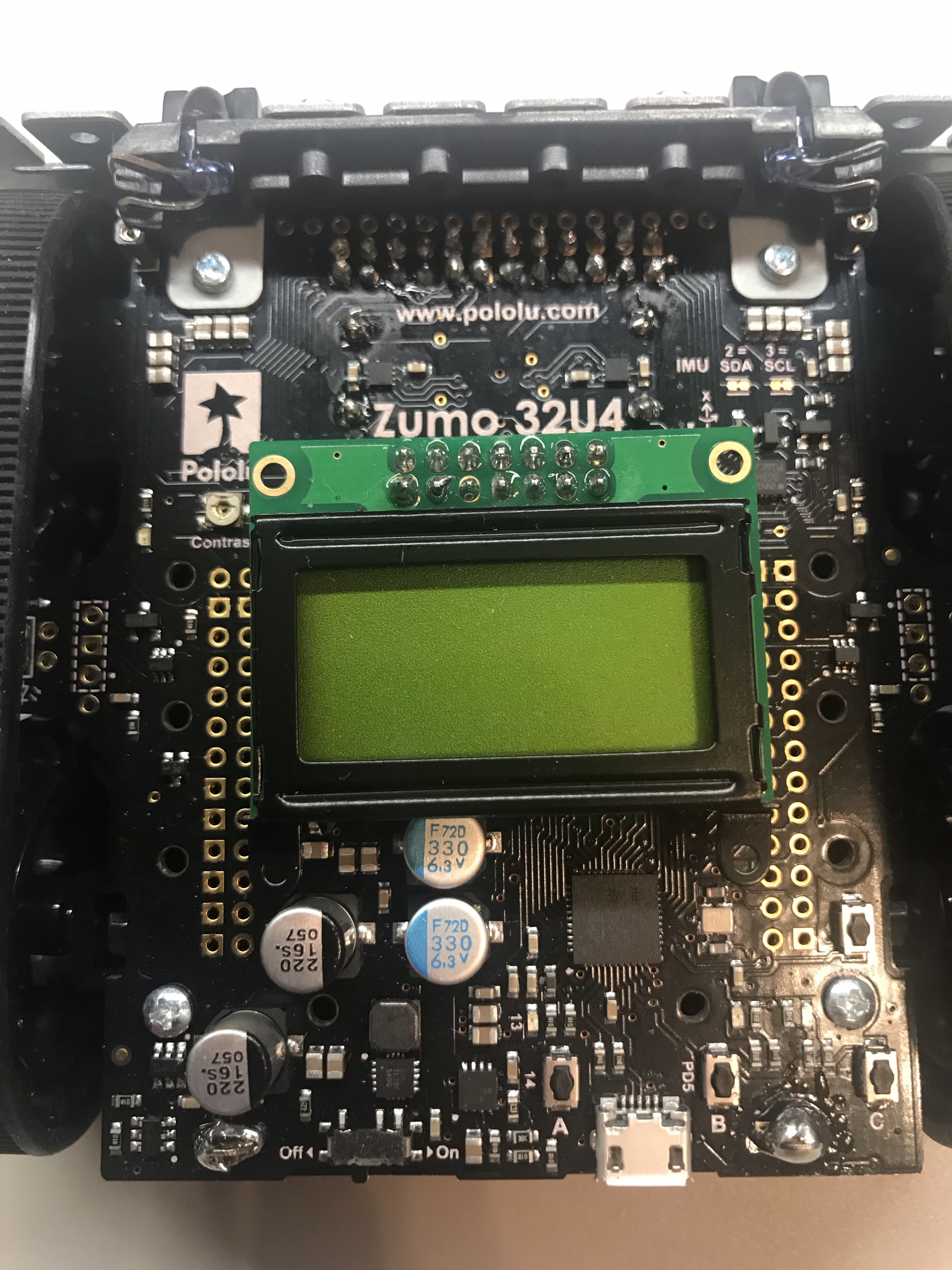
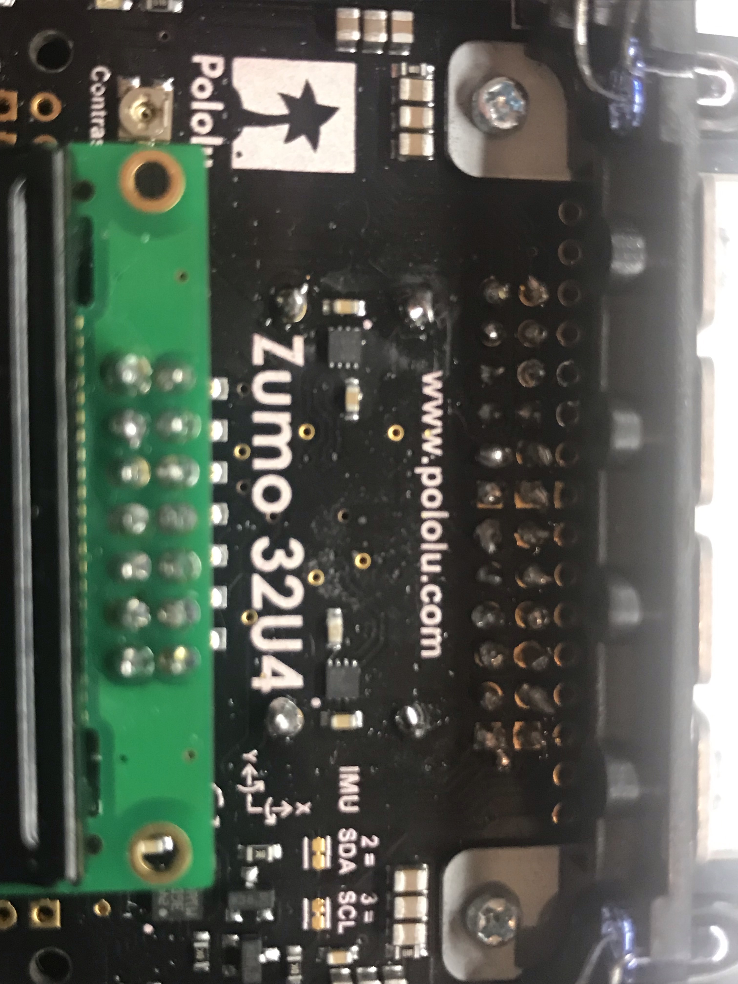
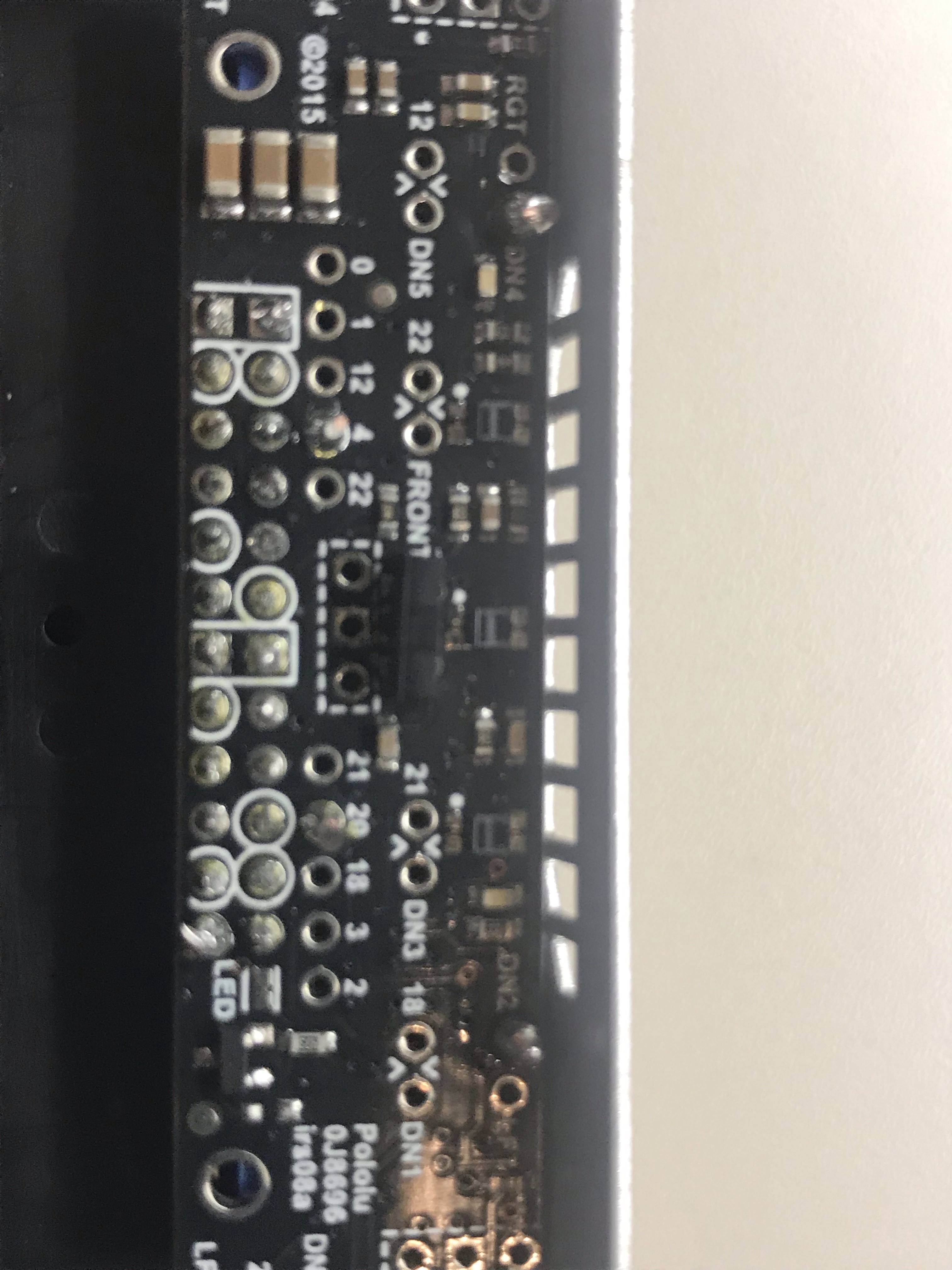
Could you try running the MotorTest example (under the “examples” folder) in the Zumo 32U4 Arduino library on your Zumo 32U4 robot (if you haven’t already) and see if you get the same behavior? Also, can you post pictures clearly showing all your soldering points on the main board?
- Amanda
Because I am adding to the Line follower code I added wires (jumpers) on the front sensor array must be installed in order to connect pin 4 to DN4 and pin 20 to DN2. I soldered these jumpers today. The motor test worked before I soldered the jumpers. Now I am getting am error message with all of the code I am using. I am extremely lost right now.
This is the error message:
/* This example uses the line sensors on the Zumo 32U4 to follow
a black line on a white background, using a PID-based algorithm.
It works decently on courses with smooth, 6" radius curves and
has been tested with Zumos using 75:1 HP motors.  Modifications
might be required for it to work well on different courses or
with different motors.

This demo requires a Zumo 32U4 Front Sensor Array to be
connected, and jumpers on the front sensor array must be
installed in order to connect pin 4 to DN4 and pin 20 to DN2. */

#include <Wire.h>
#include <Zumo32U4.h>

// This is the maximum speed the motors will be allowed to turn.
// A maxSpeed of 400 lets the motors go at top speed.  Decrease
// this value to impose a speed limit.
const uint16_t maxSpeed = 400;

Zumo32U4Buzzer buzzer;
Zumo32U4LineSensors lineSensors;
Zumo32U4Motors motors;
Zumo32U4ButtonA buttonA;
Zumo32U4LCD lcd;
Zumo32U4ButtonB buttonB;
//Zumo32U4ButtonC buttonC;

//My added code
const char fugue[] PROGMEM =
  "! O5 L16 agafaea dac+adaea fa<aa<bac#a dac#adaea f"
  "O6 dcd<b-d<ad<g d<f+d<gd<ad<b- d<dd<ed<f+d<g d<f+d<gd<ad"
  "L8 MS <b-d<b-d MLe-<ge-<g MSc<ac<a ML d<fd<f O5 MS b-gb-g"
 "ML >c#e>c#e MS afaf ML gc#gc# MS fdfd ML e<b-e<b-"
  "O6 L16ragafaea dac#adaea fa<aa<bac#a dac#adaea faeadaca";

int16_t lastError = 0;

#define NUM_SENSORS 5
unsigned int lineSensorValues[NUM_SENSORS];

// Sets up special characters in the LCD so that we can display
// bar graphs.
void loadCustomCharacters()
{
  static const char levels[] PROGMEM = {
    0, 0, 0, 0, 0, 0, 0, 63, 63, 63, 63, 63, 63, 63
  };
  lcd.loadCustomCharacter(levels + 0, 0);  // 1 bar
  lcd.loadCustomCharacter(levels + 1, 1);  // 2 bars
  lcd.loadCustomCharacter(levels + 2, 2);  // 3 bars
  lcd.loadCustomCharacter(levels + 3, 3);  // 4 bars
  lcd.loadCustomCharacter(levels + 4, 4);  // 5 bars
  lcd.loadCustomCharacter(levels + 5, 5);  // 6 bars
  lcd.loadCustomCharacter(levels + 6, 6);  // 7 bars
}

void printBar(uint8_t height)
{
  if (height > 8) { height = 8; }
  const char barChars[] = {' ', 0, 1, 2, 3, 4, 5, 6, 255};
  lcd.print(barChars[height]);
}

void calibrateSensors()
{
  lcd.clear();

  // Wait 1 second and then begin automatic sensor calibration
  // by rotating in place to sweep the sensors over the line
  delay(1000);
  for(uint16_t i = 0; i < 120; i++)
  {
    if (i > 30 && i <= 90)
    {
      motors.setSpeeds(-200, 200);
    }
    else
    {
      motors.setSpeeds(200, -200);
    }

    lineSensors.calibrate();
  }
  motors.setSpeeds(0, 0);
}

// Displays a bar graph of sensor readings on the LCD.
// Returns after the user presses A.
void showReadings()
{
  lcd.clear();

  while(!buttonA.getSingleDebouncedPress())
  {
    lineSensors.readCalibrated(lineSensorValues);

    lcd.gotoXY(0, 0);
    for (uint8_t i = 0; i < NUM_SENSORS; i++)
    {
      uint8_t barHeight = map(lineSensorValues[i], 0, 1000, 0, 8);
      printBar(barHeight);
    }
  }
}

void setup()
{
  // Uncomment if necessary to correct motor directions:
  //motors.flipLeftMotor(true);
  //motors.flipRightMotor(true);

  lineSensors.initFiveSensors();

  loadCustomCharacters();

  // Play a little welcome song
  buzzer.play(">g32>>c32");

  // Wait for button A to be pressed and released.
  lcd.clear();
  lcd.print(F("Press A"));
  lcd.gotoXY(0, 1);
  lcd.print(F("to calib"));
  buttonA.waitForButton();

  calibrateSensors();

  showReadings();

  // Play music and wait for it to finish before we start driving.
  lcd.clear();
  lcd.print(F("Go!"));
  buzzer.play("L16 cdegreg4");
  while(buzzer.isPlaying());

//My added code
   lcd.clear();
  //lcd.print(F("Press A")); //This function takes care of button debouncing.

  // Print a string
  lcd.print("NICVIC");

  // Go to the next line
  lcd.gotoXY(0, 1);

  // Print a number
  lcd.print(2018); //invalid digit "8" in octal constant. Cannot use a number larger than a 7, becuase this is reading octal

  buttonB.waitForButton();      // Code worked before I added botton functions. I think there is something wrong with my void setup........................

  lcd.clear();
}

void loop()
{
  // Get the position of the line.  Note that we *must* provide
  // the "lineSensorValues" argument to readLine() here, even
  // though we are not interested in the individual sensor
  // readings.
  int16_t position = lineSensors.readLine(lineSensorValues);

  // Our "error" is how far we are away from the center of the
  // line, which corresponds to position 2000.
  int16_t error = position - 2000;

  // Get motor speed difference using proportional and derivative
  // PID terms (the integral term is generally not very useful
  // for line following).  Here we are using a proportional
  // constant of 1/4 and a derivative constant of 6, which should
  // work decently for many Zumo motor choices.  You probably
  // want to use trial and error to tune these constants for your
  // particular Zumo and line course.
  int16_t speedDifference = error / 4 + 6 * (error - lastError);

  lastError = error;

  // Get individual motor speeds.  The sign of speedDifference
  // determines if the robot turns left or right.
  int16_t leftSpeed = (int16_t)maxSpeed + speedDifference;
  int16_t rightSpeed = (int16_t)maxSpeed - speedDifference;

  // Constrain our motor speeds to be between 0 and maxSpeed.
  // One motor will always be turning at maxSpeed, and the other
  // will be at maxSpeed-|speedDifference| if that is positive,
  // else it will be stationary.  For some applications, you
  // might want to allow the motor speed to go negative so that
  // it can spin in reverse.
  leftSpeed = constrain(leftSpeed, 0, (int16_t)maxSpeed);
  rightSpeed = constrain(rightSpeed, 0, (int16_t)maxSpeed);

  motors.setSpeeds(leftSpeed, rightSpeed);

//My added code

  // run over and over again
  // Start playing a tone with frequency 440 Hz at maximum
  // volume (15) for 200 milliseconds.
  buzzer.playFrequency(440, 200, 15);

  // Delay to give the tone time to finish.
  delay(1000);

  // Start playing note A in octave 4 at maximum volume
  // volume (15) for 2000 milliseconds.
  buzzer.playNote(NOTE_A(4), 2000, 15);

  // Wait for 200 ms and stop playing note.
  delay(200);
  buzzer.stopPlaying();

  delay(1000);

  // Start playing a fugue from program space.
  buzzer.playFromProgramSpace(fugue);

  // Wait until it is done playing.
  while(buzzer.isPlaying())

  delay(1000);
}
Correction I was able to correct the error message and was able to test the MotorTest example; everything works.
Correction, everything works when I use the motor test example. I am still unable to turn left with the code that I am using.
It sounds like there could be something wrong with your code. Can you run the original unmodified LineFollower example and see if you get the same behavior or not? Please let us know the result.
By the way, I also noticed several of your soldered joints do not look like they are making good contact with the pads on the Zumo 32U4 main board. The Adafruit Guide To Excellent Soldering has many examples of good and bad soldering joints in the “Common Soldering Problems” section of the guide as a reference. Could you try re-touching the joints and seeing if that helps?
- Amanda
Great, I will test the LineFollower example and fix my soldering joints. This is my second soldering task, so I am learning how to solder great joints.