
Hello,
My colleagues and I are testing the decay time of the QTR-MD-04RC Reflectance sensors using an oscilloscope, power supply, and function generator. We want to test the decay time between a white, gray, and black background. Notice in Figure 3 we have two cassettes with the white and gray background, respectively.
Ideally, we want to use the function generator in lieu of the Arduino with a high z mode to simulate putting a charge on the output of the OUT. We’ve powered the device with a power supply and connected to an oscilloscope to measure the delay time. However, we’re seeing a change in the rise time and not the decay time. Do you have any advice or suggestions on what we should do? For example, do we have the pin placement correct, correct oscilloscope settings, etc.
I’ve provided screenshots with captions below (Figures 1-5). Any guidance would be greatly appreciated!
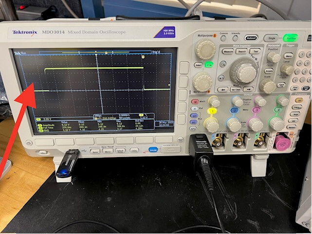
Figure 1: Oscilloscope reading that displays a rise time.
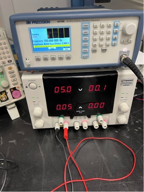
Figure 2: Power Supply and function generator settings.
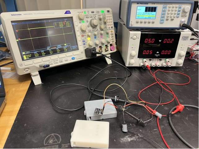
Figure 3: Full set up (oscilloscope, function generator, power supply, cassettes).
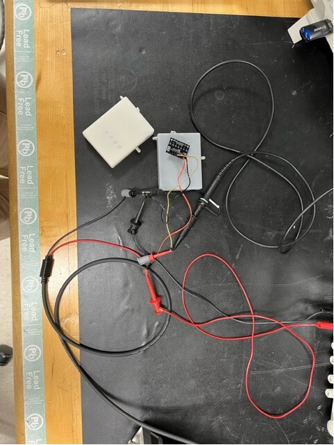
Figure 4: Top view of the connections.
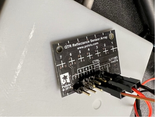
Figure 5: Close up of the selected pin connections.