
I don’t know how to do this, and I really would like to have an LCD hooked up to the micro-controller
Hello.
The answer will depend on what kind of LCD you have. If you have a parallel-interface character LCD such as the ones we sell, you can use the schematic for the Orangutan SV-168 (located under the resources tab) as a guide. Additionally, if you connect such an LCD to your Baby Orangutan in a way that matches the Orangutan SV-168 connections, then the LCD code from the Pololu AVR library should work for you.
- Ben
Here is an example:
It is built exactly as Ben outlined. I was able to use 3Pi code without significant changes.
dear Pololu guys,
Can I attach a larger (like 2x16 characters) LCD indicator to Baby Orangutan, using same 14-pin connection and same software code?
like this one: https://www.pololu.com/catalog/product/772
If not - what changes may be needed?
Thanks!
Hi, RiO.
The 16x2 and 20x4 LCDs we sell all use the same HD44780 interface, so you can pretty much swap one for another without changing your hardware or software. If you choose a model with a backlight, you might want to make the necessary additional connections to power the LEDs.
- Ben
Hi Guys,
I have connected a 20x4 (this one: pololu.com/catalog/product/676) to my BabyO B-168 but i have not been able to communicate with it at all. As suggested here, I have made all the connections following the SV-168 design using a flat ribbon cable and it does not work for me. I do have connected to the same controller a small DC motor and developed all the programming I need to run it forward, reversed, reciprocating, etc. and everything works. The control of the motor is hard coded. However, I am using the standard Pololu AVR Library for time keeping and the Red LED control without issues at all. I have follow the same SV-168 design to read the input form some PB switches and the state of the switches is read using the standard Pololu AVR Library as well and it all worked at first try without any issues. But as soon as I add a clear(), print(), or any other LCD related function the code execution halts at the call of that function as if the LCD does not respond at all. The only sign of life I get from the display is the backlight being on. I have checked and rechecked all my connections a few times. I have even ordered a and tried a second display and I get the same response, nothing at all. I hate to come here with such a generic question without any more clues about what is going on but this is all I have. I hope you can help with some clues on how to debug the problem or where to start.
Thanks in advance
Hello, octavio.
I’m sorry for the delayed reply. Have you tried adjusting the LCD contrast voltage? It sounds like you have other components, such as switches) connected to the LCD lines. Can you first try getting the LCD to work without anything else on the line? Can you post a picture of your setup in a way that makes it clear what pins on the Baby Orangutan are connected to what pins on the LCD? How are you powering the backlight?
- Ben
Hi Ben,
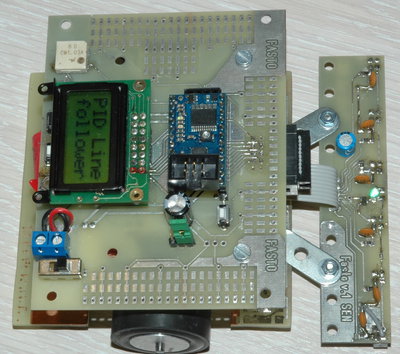
Thanks for your response. As requested, I am attaching a couple of pictures of my setup.
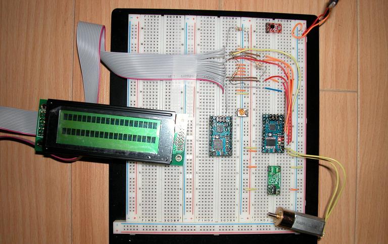

Unfortunately the actual wiring of the LCD-BabyO interface are not clearly discerned from those pictures.
As you can see, the contrast adjustment is ok since the 1st picture shoes the 1st and 3rd row displaying solid blocks (or is it 2nd and 4th row? I do not know at this point).
The whole system is powered at 6V through a Power Switch SV (pololu.com/catalog/product/750).
Related to the wiring, since is not clear in the picture, this is how the LCD is interconnected with the BabyO:
LCD BabyO
1 Vss
2 VDD
3 Vo
4 RS 10 PD2
5 R/W 3 PB0 (with a 4.7K pull down resistor)
6 E 11 PD4
7 DB0 Connected to GND
8 DB1 Connected to GND
9 DB2 Connected to GND
10 DB3 Connected to GND
11 DB4 4 PB1
12 DB5 6 PB4
13 DB6 7 PB5
14 DB7 12 PD7
All this was done following the SV-168 Schematic Diagram.
Regarding the PB switches, I just manually connect a pull down resistor to PB5 to get simulate the switch operation.
I hope you can spot my error. It got to be something silly.
Cheers.
Octavio
One more thing I would like to add. Here is a portion of the code on the main routine:
	delay (1000);
	red_led (ON);
	delay (1000);
	red_led (OFF);
	delay (1000);

//	clear ();
//	print ("H");

	red_led (ON);
	delay (1000);
	red_led (OFF);
	delay (1000);
If i remove the comment slashes and call the clear() function say. The program will freeze and the red LED won’t flash the second time. If comment it out, the the program continues, the red LED flashes a second time and the rest of the code works.
Cheers
Octavio
Thanks for the info. I’ll take a look at it all in more detail tomorrow, but one thing I notice is that you have the red wire of your ribbon cable connected to power (Vdd). Typically, the red wire denotes pin 1, but pin 1 of the LCD should connect to ground (Vss). Are you connecting the red wire to pin 2 of the LCD? From bottom to top, what pins do the ribbon cable wires connect to on the LCD?
- Ben
Boy! You really have a good eye.
Pin 1 of the LCD is connected to ground (Vss) as you have mentioned it. The red wire on the ribbon cable is actually LCD’s pin 2, and from that starting point, the ribbon cables carries the following pin order: 2, 1, 4, 3, 6, 5, 8, 7, etc. The reason is that the Shrouded Box Header (2x8-Pin Male) is soldered to the back of LCD and not to the front of it (see the 1st picture I sent before). This reverses the pin order the way I just described on the ribbon cable. I did this because otherwise the Shrouded Box Header will interfere with the mounting of the display on the final fixture we are fabricating. The front of the LCD gets mounted through a cut-out hole leaving a 4mm gap between the LCD’s PCB and the fixture’s wall. However, I did check again yesterday all the point to point connections with a multimeter and all seems to be correct. I did this checking directly between the LCD’s pins and the BabyO’s pins, ground, etc.
I am including again the I/O interface between the LCD and the BabyO since it looked messy on my previous posting.
LCD       BabyO
1 Vss
2 VDD
3 Vo
4 RS      10 PD2
5 R/W      3 PB0 (with a 4.7K pull down resistor)
6 E       11 PD4
7 DB0        Connected to GND
8 DB1        Connected to GND
9 DB2        Connected to GND
10 DB3       Connected to GND
11 DB4     4 PB1
12 DB5     6 PB4
13 DB6     7 PB5
14 DB7    12 PD7
In the absence of wiring errors, the most frequent reason that an LCD display fails to respond is due to timing errors. Unless the “busy” line is sampled and used to implement the delay, software delays are usually implemented as wait loops. If one or more of these are too short the LCD will fail to respond and nothing will happen.
I’m not familiar enough with the Pololu library code to know off-hand which timing method is implemented, but if software delays are used, try increasing (e.g. doubling) the delay associated with both the send_command and send_character routines. You might also take a look at the initialization code and increase the delays there. Even though you are using a Pololu display, the clock generator on the LCD controller is based on RC timing and subject to wide variations. After you get it working, you can decrease the delay times until it stops working again, in order to determine what is actually required.