I need help getting a Sharp distance sensor working with the 3pi.
Following the example in this website for 3pi Wall Follower, I’ve connected a Sharpe 2Y0A21 10-80cm range sensor to the 3pi. I’m hoping to experiment with the Sharp sensor to see how well it senses various objects depending on their size, distance, reflectivity/color of surface etc. for possible use in a hockey-bot. Thus, I’ve only connecting what the example uses as the LEFT wall sensor.
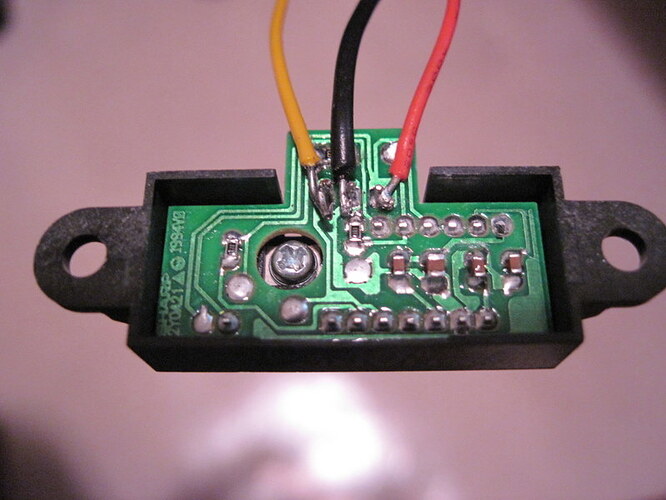
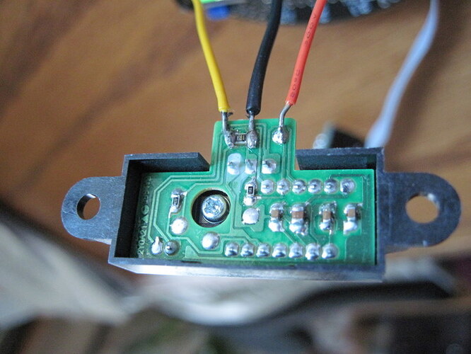
So, I removed the 3pi jumper for the ADC7 to the user trim pot. I’ve soldered 3 wires to the Sharp sensor Red, Black, and White (ok my wire is Yellow). Then I soldered these to the 3pi board pin/holes for Vcc, Gnd, and ADC7 (respectively) as shown in in the example documentation. (I’m assuming the silkscreen label AD7 is equal to the ATmega ADC7 port.)
For software, since I want to observe the reading from the Sharp sensor, I thought I could just run the 3pi-demo-program/test.c as-is, select the trim pot test, and see (and hear) the value.
The code looks simple enough. I gave it a try but LCD display shows a value of “71” no matter what I point the Sharp sensor at, far or near. The reading never changes.
Am I missing something? The code is show below. I ran as-is from Pololu first. I tried replacing calls to read_trimpot to analog_read(7) but no change. (I turned off the tone to stop annoying me.)
void pot_test()
{
	long start = get_ms();
	char elapsed_ms;
	int value;

	set_analog_mode(MODE_10_BIT);
	print_long(read_trimpot());
	print("   "); // to clear the display

	while((elapsed_ms = get_ms() - start) < 100)
	{
		value = read_trimpot();

		//play_frequency(value, 200, 15);	// silence please

		if(value < elapsed_ms*10)
		{
			red_led(0);
			green_led(1);
		}
		else
		{
			red_led(1);
			green_led(0);
		}
	}
}
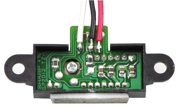
The only deviation I can see from the example wall follower is that the photo of the underside of the Sharpe (labeled “Sharp distance sensor with connected wires and double sided tape”) looks slightly different. The screw and all the layout looks identical but on my part the White and Black wires are very close and the right-most solder point (Red wire) is spaced further away. Also my part is labeled “2Y0A21” where as the example photo shows a Sharp “GP2D12”. (Hmmm. I wish I’d ordered the little cable. Says it works with the 30cm would it work with the 80cm part too?)
Also, I guess looking closely now I soldered to the outer most 3 solder points whereas the example photo almost looks like he soldered to the 3 points that are the 2nd row in from the edge.
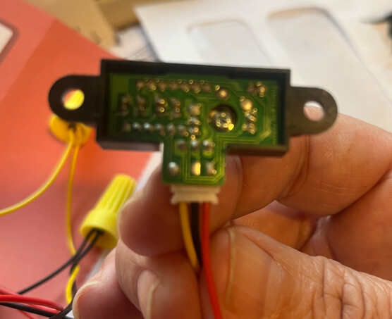
Is that my problem perhaps? If so, can someone tell me if the 99 cent cable works for the 80cm part? My soldering skills won’t let me work at such small detail.
Thanks


