Help with scaling the axes of the accelerometer, gyroscope and magnetometer

I am asking a question to the community of experts.
How do I properly scale the gyroscope and accelerometer axes to use with the example code?
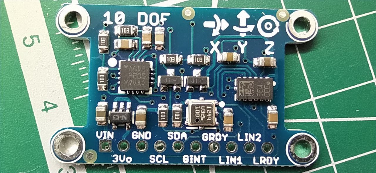
I have a board with sensors lsm303dlh and l3gd20.


I also have the MPU9250, BMI160 and LSM6DS3 sensors, but I will return to them after I manage to run the sensors described in the question header with the example code.

To work with these sensors I use libraries

#include <Adafruit_LSM303.h>
#include <L3G.h>

I didn’t like the

#include <LSM303.h>

library, but I’ll tell you about that a little later, why I don’t use it to work with the accelerometer and magnetometer.
It was not easy to determine the model of my sensors, but from indirect evidence I realized that a gyroscope is l3gd20, and an accelerometer with magnetometer is lsm303dlh.
I have previously used these sensors in other implementations of the Madgwick and Mahony filters and obtained the raw values as follows:

L3G gyro;
Adafruit_LSM303 accel_mag;

// gyro
gyro.init();
gyro.enableDefault();
gyro.read();

gx = gyro.g.x;
gy = gyro.g.y;
gz = gyro.g.z;

// accel + mag
accel_mag.begin();
accel_mag.read();

ax = accel_mag.accelData.x;
ay = accel_mag.accelData.y;
az = accel_mag.accelData.z;

mx = accel_mag.magData.x;
my = accel_mag.magData.y;
mz = accel_mag.magData.z;

The code is not complete and is not code at all, but just to understand how I get the data.
Initially I took the code from the example, but it did not compile out of the box and it was decided to rewrite the code for other sensors and also get rid of so many *ino files.
And so, I get raw data from the gyroscope for each X, Y, Z axis.

  uint8_t xlg = Wire.read();
  uint8_t xhg = Wire.read();
  uint8_t ylg = Wire.read();
  uint8_t yhg = Wire.read();
  uint8_t zlg = Wire.read();
  uint8_t zhg = Wire.read();

  // combine high and low bytes
  g.x = (int16_t)(xhg << 8 | xlg);
  g.y = (int16_t)(yhg << 8 | ylg);
  g.z = (int16_t)(zhg << 8 | zlg);

Using the library, I can change what angular velocity the sensor will measure in terms of the entire scale, which is +32752 and -32736, although according to the library datasheet it should be 32768.
And because the ADC is 16-bit, it’s actually 65536 - but I didn’t delve into this issue for the time being, because with a different code the orientation of the corners was determined and that suited me.
I entered a definition to assign the desired rotation speed, for example:
#define GYRO_RANGE 250.0f
Received the raw value of angular velocity
gx = gyro.g.x;
And he simply performed mathematical calculations and received a scaled value of angular velocity.
gxScaled = (gx - gyroOffSets[X_]) * GYRO_RANGE / 32768.0;
If I register the value of the angular velocity, for example

 // 0x00 = 0b00000000
 // FS = 00 (+/- 250 dps full scale)
 //writeReg(CTRL_REG4, 0x00);
 // FS = 01 (+/- 500 dps full scale)
 writeReg(CTRL_REG4, 0x01);
 // FS = 10 (+/- 2000 dps full scale)
 // writeReg(CTRL_REG4, 0x10);

500 or 2000 DPS also changed
#define GYRO_RANGE 500.0f
or
#define GYRO_RANGE 2000.0f
I received approximately the same acceleration values from the accelerometer.
Also introduced define
#define ACCEL_RANGE 2.0f
Also changed registers in the library

write8(LSM303_ADDRESS_ACCEL, LSM303_REGISTER_ACCEL_CTRL_REG1_A, 0x27);
 // Y - OFF 0b100101
 // write8(LSM303_ADDRESS_ACCEL, LSM303_REGISTER_ACCEL_CTRL_REG1_A, 0x25);
// 0b100111
// LSM303_REGISTER_ACCEL_CTRL_REG1_A - 0x20
// 0100
// ODR3 ODR2 ODR1 ODR0 Power mode and ODR selection
// 0 0 0 0 Power-down mode
// 0 0 0 1 Normal / low-power mode (1 Hz) - 0x17
// 0 0 1 0 Normal / low-power mode (10 Hz) - 0x27
// 0 0 1 1 Normal / low-power mode (25 Hz) - 0x37
// 0 1 0 0 Normal / low-power mode (50 Hz) - 0x47
// 0 1 0 1 Normal / low-power mode (100 Hz) - 0x57
// 0 1 1 0 Normal / low-power mode (200 Hz)
// 0 1 1 1 Normal / low-power mode (400 Hz)
// 1 0 0 0 Low-power mode (1.620 kHz)
// 1 0 0 1 Normal (1.344 kHz) / low-power mode (5.376 kHz)
// 0111
// LPen
// Low-power mode enable. Default value: 0
// (0: normal mode, 1: low-power mode)
// Zen
// Z-axis enable. Default value: 1
// (0: Z-axis disabled, 1: Z-axis enabled)
// Yen
// Y-axis enable. Default value: 1
// (0: Y-axis disabled, 1: Y-axis enabled)
//Xen
// X-axis enable. Default value: 1
// (0: X-axis disabled, 1: X-axis enabled)

And then I scaled the resulting raw acceleration value.
In the example code in a file* I get gyroscope, accelerometer and magnetometer data.
And here the incomprehensible moments begin.
In the source code of the example, defines are assigned
// #define Gyro_Scaled_X(x) (x*ToRad(Gyro_Gain_X)) //Return the scaled ADC raw data of the gyro in radians for second
which did not want to be compiled in the Arduino environment.
I had to replace them with simple defines, without math

#define DEG_TO_RAD (M_PI / 180.0)
#define RAD_TO_DEG (180.0 / M_PI)

And now to get the values of the vector of the gyro and accelerometer I write like this
Gyro_Vector[0]=gyro_x * (GYRO_RANGE / 32768.0) * DEG_TO_RAD; //gyro x roll
The second problem is the strange scaling of the accelerometer axes.
For some reason, the authors of the example coarsened the values of a 16-bit ADC by bit shifting.
Introduced a strange variable GRAVITY with an even stranger value of 256!
Why do such strange things in a place where there is already no physical connection to the entity, except for the ADC bit capacity.
Maybe I don’t understand something?
In general, I assembled the code and it started working.
If I bet
#define OUTPUTMODE 1
There is practically no drift, but over time, nevertheless, the angles move slightly away from the initial values.

After start

32
42
-46
-534
-124
14361
Orientation: 0.00 -0.00 -360.00
Orientation: 0.01 -0.01 -0.00

After moving


I tried calibrating accelerometers with gyroscopes, as well as a strange magnetometer calibration based on min and max values.
By the way, what kind of strange calibration is this?
Is this calibration of soft iron and that’s all?

Result with this code

#include <Wire.h>
#include <LSM303.h>

LSM303 compass;
LSM303::vector<int16_t> running_min = {32767, 32767, 32767}, running_max = {-32768, -32768, -32768};

char report[80];

void setup() {
  Serial.begin(115200);
  Wire.begin();
  compass.init();
  compass.enableDefault();
}

void loop() {  
  compass.read();
  
  running_min.x = min(running_min.x, compass.m.x);
  running_min.y = min(running_min.y, compass.m.y);
  running_min.z = min(running_min.z, compass.m.z);

  running_max.x = max(running_max.x, compass.m.x);
  running_max.y = max(running_max.y, compass.m.y);
  running_max.z = max(running_max.z, compass.m.z);
  
  snprintf(report, sizeof(report), "min: {%+6d, %+6d, %+6d}    max: {%+6d, %+6d, %+6d}",
    running_min.x, running_min.y, running_min.z,
    running_max.x, running_max.y, running_max.z);
  Serial.println(report);
  
  delay(100);
}
min: {  +198,   -377,   -270}    max: {  +206,   -375,    -77}
min: {  +198,   -377,   -270}    max: {  +206,   -374,    -77}
min: {  +198,   -378,   -270}    max: {  +207,   -374,    -77}

The result of the same code when I don’t bit shift the results of the magnetometer values.

min: {-14592, -32001, +26878} max: {-11520, +29951, +29438}
min: {-14592, -32001, +26878} max: {-11520, +29951, +29694}

If you rotate the board, the values will change.

min: {-32258, -32513, -32514}    max: {+32767, +32767, +32766}

For me, it doesn’t make any difference in the work… but this is my purely personal opinion.
This moment is of greater interest - for some reason, when setting the gyroscope to 250 degrees per second, and turning the board with sensors by - 90 degrees, the angle calculated by the example code turns by -80, then I return the board to the horizon and the angle shows ± 0 degrees, then I change the board’s roll angle to +90 degrees and the example code calculates +100 degrees for me.
At the same time, the calibration of the axes of gyroscopes and accelerometers is the same.
Then there is another strange thing - when I change the roll angle, the pitch angle does not change.
But if I start changing the pitch angle, for example from 0 to -60, then after -60 the roll angle begins to change and becomes -30 degrees.
And vice versa, if I change the pitch angle from 0 to +60, then after +60 degrees the roll angle will begin to change and become +30 degrees.
Also, when the pitch angle changes, for some reason the yaw angle also changes.
Well, the worst thing about all this is that if, after turning on the board and starting the program, you take the board from a horizontal position and smoothly begin to change the roll and pitch angles, then after returning to the horizontal position, the angles will be ±0 degrees.
If I change the roll or pitch angle sharply, that is, I quickly tilt the board to the left and then sharply to the right, then when I leave the board alone after such roll or pitch jerks, the angle will no longer be 0 and it never returns to zeros.
It feels like the example code doesn’t use the I values of the accelerometers and magnetometers to correct for drift and serve as reference vectors to return the board to zero positions.
I have attached the code of the redesigned example, although the original code of the example is quite old, but I hope someone can help me figure out the problems and tell me what I’m doing wrong.
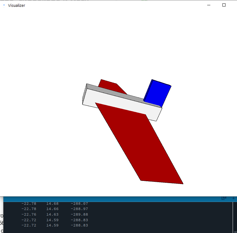
I’m weak in python and therefore use Processing to visually display the position of the board with sensors.
minimu-9-ahrs-arduino.rar (22.0 KB)
The archive contains example code and a GUI with a program for processing 4.2
Why didn’t you use the #include <LSM303.h> library?
Because when using it, the magnetometer values are only three-digit, because the library defines my sensor as
device_DLHC

// Reads the 3 magnetometer channels and stores them in vector m
void LSM303::readMag(void)
{
  Wire.beginTransmission(mag_address);
  // If LSM303D, assert MSB to enable subaddress updating
  // OUT_X_L_M comes first on D, OUT_X_H_M on others
  Wire.write((_device == device_D) ? translated_regs[-OUT_X_L_M] | (1 << 7) : translated_regs[-OUT_X_H_M]);
  last_status = Wire.endTransmission();
  Wire.requestFrom(mag_address, (byte)6);

  unsigned int millis_start = millis();
  while (Wire.available() < 6) {
    if (io_timeout > 0 && ((unsigned int)millis() - millis_start) > io_timeout)
    {
      did_timeout = true;
      return;
    }
  }

  byte xlm, xhm, ylm, yhm, zlm, zhm;

  if (_device == device_D)
  {
    // D: X_L, X_H, Y_L, Y_H, Z_L, Z_H
    xlm = Wire.read();
    xhm = Wire.read();
    ylm = Wire.read();
    yhm = Wire.read();
    zlm = Wire.read();
    zhm = Wire.read();
  }
  else
  {
    // DLHC, DLM, DLH: X_H, X_L...
    xhm = Wire.read();
    xlm = Wire.read();

    if (_device == device_DLH)
    {
      // DLH: ...Y_H, Y_L, Z_H, Z_L
      yhm = Wire.read();
      ylm = Wire.read();
      zhm = Wire.read();
      zlm = Wire.read();
    }
    else
    {
      // DLM, DLHC: ...Z_H, Z_L, Y_H, Y_L
      zhm = Wire.read();
      zlm = Wire.read();
      yhm = Wire.read();
      ylm = Wire.read();
    }
  }

  // combine high and low bytes
  m.x = (int16_t)(xhm << 8 | xlm);
  m.y = (int16_t)(yhm << 8 | ylm);
  m.z = (int16_t)(zhm << 8 | zlm);
}

While the library
#include <Adafruit_LSM303.h>
Gives the full value of raw magnetometer data
65320,65204,65453

To address a few specific details: It looks like you probably have an LSM303DLHC, which has a pretty distinctive rectangular shape (on the right side of your board); the LSM303DLH has a square package.

Early versions of our LSM303 library truncated the magnetometer readings to 12 bits because earlier LSM303 sensors only had 12 bit precision (the lowest 4 bits of the 16-bit reading were always 0), but recent versions of the library should not do that anymore. Did you check that you were using the latest version?

If you want to try getting your board working with our MinIMU9-AHRS program (which I’d generally expect to work, since it looks like it has the same sensors as the MinIMU-9 v2), we’d be happy to address specific issues you have with the original code. However, offering general assistance with code is typically beyond the scope of our technical support, especially in cases like this where it seems like you are not using any of our products and have made significant changes to our example program code.

Kevin

1 Like

Good afternoon.
Yes, I have sensors lsm303dlh and l3gd20.
I didn’t change the example code radically, I just moved away from a large number of *ino files, replacing them with *h files.
If you can tell me, I need help with correctly receiving data from the gyroscope and accelerometer.
As far as I understand, in the native example the gyroscope is set to an operating mode of 2000 DPS.

// gyro.writeReg(L3G::CTRL_REG4, 0x20); // 2000 dps full scale 0b00110000
// gyro.writeReg(L3G::CTRL_REG1, 0x0F); // normal power mode, all axes enabled, ODR 95Hz, Cut-Off 12.5 Hz - 0b00001111

And the data from the 8G accelerometer
// compass.writeReg(LSM303::CTRL_REG4_A, 0x28); // 8 g full scale: FS = 10; high resolution output mode
I like the expression I heard somewhere - “garbage in, garbage out.”
Therefore, I study this issue in great detail and want to understand it.
In ASCII plotter

#include <Wire.h>
#include <String.h>
#include <L3G.h>
#include <LSM303.h>

LSM303 compass;
L3G gyro;

void setup() {
  Serial.begin(115200);
  Wire.begin();
  if (!gyro.init())
  {
    Serial.println("Failed to autodetect gyro type!");
    while (1);
  }
  if (!compass.init())
  {
    Serial.println("Failed to initialize compass!");
    while (1);
  }
  gyro.enableDefault();
  compass.enableDefault(); 
}

void loop() {
  static int barcounter = 0;
  String spacestring = "                                                                ";
  String barstring = "----------------------------------------------------------------";
  String outstring;

  barcounter++;
  if(barcounter==10){
    barcounter=0;
    outstring=barstring;
    outstring += millis()/100;
  }
  else outstring=spacestring;

  gyro.read();
  compass.read();

  //gyro axes are drawn with thin lines, accelerometer are drawn with thick lines
  outstring.setCharAt(11+((int)gyro.g.x)/3277, ':');
  outstring.setCharAt(11+((int)compass.a.x)/3277, 'X');
  outstring.setCharAt(32+((int)gyro.g.y)/3277, ':');
  outstring.setCharAt(32+((int)compass.a.y)/3277, 'X');
  outstring.setCharAt(53+((int)gyro.g.z)/3277, ':');
  outstring.setCharAt(53+((int)compass.a.z)/3277, 'X');   
  Serial.println(outstring);

  delay(20);
}

In raw value is divided by 3277.
That is, raw default values have a maximum digit in 32768.
Output data then I moved breadboard.

-----------X---:---------------:X--------------------:-----X----1907
           X    :              :X                    :   X
           X      :             :X                  :   X
           X      :             : X                  :  X
            X    :              : X                  :  X
           X     :             :  X                  :  X
           X      :             :X                  :   X
           X    :               : X                  :  X
           X   :                :  X                 : X
           X   :                :  X                 : X
-----------X---:----------------:--X----------------:--X--------1909
           X :                  :   X                : X
           X:                   :   X                : X
           X                    :  X                 : X
         : X                    :   X                : X
       :   X                    :   X                : X
       :   X                    :   X                : X
        :  X                    :   X                : X
         : X                    :  X                 : X
        :  X                    :  X                 : X
-------:---X--------------------:--X-----------------:--X-------1912
       :   X                    : X                  :  X
       :   X                     :X                  :  X
       :   X                    : X                  :  X
       :   X                    : X                  :  X
        :  X                    :X                   :  X
         : X                    :X                   :  X
          :X                    :X                   :  X
          :X                    :X                   :   X
         : X                    :X                   :   X
---------:-X--------------------:X-------------------:---X------1914

The example code processes values from the gyroscope and gives them higher priority than data from the accelerometer - this is primarily set by the code itself in matrix mathematics, and is also set by the coefficient of the integral component.
And here is one of the incomprehensible moments of the code for me - why set the accelerometer to the maximum register in order to receive 8G data and then reduce it to 256 values?
As I already wrote, to work with the accelerometer I use the #include <Adafruit_LSM303.h> library
If I set the registers to the value of the accelerometer
// 0x08 = 0b00001000 2g
then I get the data at rest, for the Z axis, for example Z = 14512 (the Z axis looks up).
If I set the registers to the value of the accelerometer
// 0x28 = 0b00111000 8g
then I get the data at rest, for the Y axis, for example Y = 4160, (the y axis looks down)
To test the program in operation, I set the gyroscope to 2000 DPS and the accelerometer to 2G.
I collect the code and display data about:
Gyro_Vector and Accel_Vector in the serial port.
If the angular velocity is more or less true, but the accelerations are generally some kind of nonsense
I’m starting to figure it out, and I understand that offset values are added to the raw value from the accelerometer

   for(int i=0;i<32;i++) // We take some readings...
     {
     Read_Gyro();
     Read_Accel();
     for(int y=0; y<6; y++) // Cumulate values
       AN_OFFSET[y] += AN[y];
     delay(20);
     }

   for(int y=0; y<6; y++)
     AN_OFFSET[y] = AN_OFFSET[y]/32;

   AN_OFFSET[5]-=GRAVITY*SENSOR_SIGN[5];

In my case, when the data from the accelerometer axis is equal to -+16384, I set the same value for the GRAVITY coefficient and get complete nonsense.
As a result, I temporarily assigned GRAVITY = 1;
The code began to work more or less; when the board’s roll angle changes, the roll and orientation angles also change.
When I change the pitch angle of the board, the pitch angle and orientation change.
But there is a strange thing: the yaw angle does not respond, i.e. does not change when the board is positioned horizontally, if I change the pitch angle, for example by +20 degrees, then the yaw axis begins to react to the movements of the board.
I tried to deal with the signs int SENSOR_SIGN[9], but this is even more confusing and does not bring the desired result.
Although sensors LSM6 and L3G + LSM303 have the same direction of the x, y, z axes and the direction of rotation, the change of signs is not informative.
В итоге для свое платы я подобрал значения знаков такими:
int SENSOR_SIGN[9] = {1,1,-1,1,1,1,-1,-1,-1};
As a result, I have several problems with the code:

  1. I don’t understand in what form to receive data from gyroscopes and accelerometers and how to scale them
  2. unclear logic of how offsets work
  3. complex system for entering the direction of the axes using -+ signs
  4. not an obvious dependence of the yaw angle on roll and pitch
  5. inability to calibrate the magnetometer using hard and soft iron (hard iron calibration provides virtually no benefit)

Also, please tell me, if at the start of the program I receive acceleration offset data in the serial port, do I need to include it in the same form in the code?

Pololu MinIMU-9 + Arduino AHRS
-5
-3
0
-75
26
3657

Into
int AN_OFFSET[6]={-5,-3,0,-75,26,3657}; //Array that stores the Offset of the sensors

Also, a section of the code remains not entirely clear

// Calculate the magnitude of the accelerometer vector
Accel_magnitude = sqrt(Accel_Vector[0]*Accel_Vector[0] + Accel_Vector[1]*Accel_Vector[1] + Accel_Vector[2]*Accel_Vector[2]);
Accel_magnitude = Accel_magnitude / GRAVITY; // Scale to gravity.
// Dynamic weighting of accelerometer info (reliability filter)
// Weight for accelerometer info (<0.5G = 0.0, 1G = 1.0 , >1.5G = 0.0)
Accel_weight = constrain(1 - 2*abs(1 - Accel_magnitude),0,1); //

With my data and GRAVITY = 1 I get the following values of acceleration magnitude and weight.

 Serial.print(Accel_magnitude);
 Serial.print(" ");
 Serial.print(Accel_weight);

Are these Accel_magnitude and Accel_weight values plausible?
Is the GRAVITY parameter selected correctly?

0.97 0.95
0.97 0.95
0.34 0.00
0.34 0.00
1.10 0.81
1.10 0.81
1.09 0.81
1.09 0.81
1.16 0.68
1.16 0.68
0.37 0.00
0.37 0.00
0.37 0.00
0.58 0.16
0.58 0.16
0.68 0.36
0.68 0.36
1.28 0.43
1.28 0.43
1.28 0.43
0.86 0.73
0.86 0.73
0.83 0.66
0.83 0.66
0.85 0.71
0.85 0.71

Please tell me how to add work with the accelerometer to full scale in the code?
Why cut the values to 256?
This is the main point that introduces many problems in understanding and adapting the code for other sensors.
I have attached a slightly modified code:
minimu-9-ahrs-arduino_v2.rar (16.6 KB)
I managed to achieve stability in the roll and pitch angles, but sometimes when moving the board with sensors, the output angles freeze (slow down) a little.
I tried playing with the parameter float G_Dt=0.02; but this didn’t help much.
It is necessary to double-check the code, there may be some “delays”.
There remains the problem of yaw, which only changes when the board is not in a horizontal position.
I would appreciate any hints. :grinning:
P.S. I figured out the yaw, I forgot to convert radians to degrees when outputting.

// Serial.print(yaw);
Serial.print(yaw * RAD_TO_DEG);

Therefore, yaw rotations were in radians and practically invisible visually.
The main thing that I can’t adjust is the effect of roll on pitch.
Although these two angles should be independent.
If I take the board, make a left roll and begin to rotate around the axis, then the pitch floats away and the angles show nonsense.
The most interesting thing is that a simple Mahony filter with certain coefficients was able to eliminate the influence on pitch when changing roll and swaying from side to side

void Mahony_update(float ax, float ay, float az, float gx, float gy, float gz, float deltat) {
   float recipNorm;
   float vx, vy, vz;
   float ex, ey, ez; //error terms
   float qa, qb, qc;
   static float ix = 0.0, iy = 0.0, iz = 0.0; //integral feedback terms
   float tmp;

   // Compute feedback only if accelerometer measurement valid (avoids NaN in accelerometer normalization)
   tmp = ax * ax + ay * ay + az * az;
   if (tmp > 0.0)
   {

     // Normalize accelerometer (assumed to measure the direction of gravity in body frame)
     recipNorm = 1.0 / sqrt(tmp);
     ax *= recipNorm;
     ay *= recipNorm;
     az *= recipNorm;

     // Estimated direction of gravity in the body frame (factor of two divided out)
     vx = q[1] * q[3] - q[0] * q[2];
     vy = q[0] * q[1] + q[2] * q[3];
     vz = q[0] * q[0] - 0.5f + q[3] * q[3];

     // Error is cross product between estimated and measured direction of gravity in body frame
     // (half the actual magnitude)
     ex = (ay * vz - az * vy);
     ey = (az * vx - ax * vz);
     ez = (ax * vy - ay * vx);

     // Compute and apply to gyro term the integral feedback, if enabled
     if (Ki > 0.0f) {
       ix += Ki * ex * deltat; // integral error scaled by Ki
       iy += Ki * ey * deltat;
       iz += Ki * ez * deltat;
       gx += ix; // apply integral feedback
       gy += iy;
       gz += iz;
     }

     // Apply proportional feedback to gyro term
     gx += Kp * ex;
     gy += Kp * ey;
     gz += Kp * ez;
   }

   // Integrate rate of change of quaternion, q cross gyro term
   deltat = 0.5 * deltat;
   gx *= deltat; // pre-multiply common factors
   gy *= deltat;
   gz *= deltat;
   qa = q[0];
   qb = q[1];
   qc = q[2];
   q[0] += (-qb * gx - qc * gy - q[3] * gz);
   q[1] += (qa * gx + qc * gz - q[3] * gy);
   q[2] += (qa * gy - qb * gz + q[3] * gx);
   q[3] += (qa * gz + qb * gy - qc * gx);

   // renormalize quaternion
   recipNorm = 1.0 / sqrt(q[0] * q[0] + q[1] * q[1] + q[2] * q[2] + q[3] * q[3]);
   q[0] = q[0] * recipNorm;
   q[1] = q[1] * recipNorm;
   q[2] = q[2] * recipNorm;
   q[3] = q[3] * recipNorm;
}

But a cool filter with rotating matrices for 1000 lines of code could not.
I probably just didn’t set up the filter well…

As far as I understand the code, it did not convert raw values from the gyroscope to degrees/sec and acceleration to G?

Accelerations are generally transmitted in their raw form, except that the offsets are subtracted and the directions of the axes are set.
Typically, data from the gyroscope is fed to the filter input in rad/sec and acceleration in G.
Here in the code everything is confusing and opaque, so I want to figure it out and rewrite the code for other sensors and in general, so that any sensors can be integrated into the code without problems.