
Hello,
this is my first post on the forum
I am building a fast line follower
using:
Arduino Nano, pololu QTR8RC and DRV8835 with N20 metal gear motors.
Actually, i managed to make it run using a PID…It works great when following curves and straight lines but there are too many errors when taking sharp turns ( angle 45, or 90 deg); the robot is turning in the wrong directions sometimes ( because the robot is not exactly at the middle of the line at the beginning of some turns…so it goes in the wrong direction sometimes).
After some research on internet…i saw someone suggesting to add an additional code
https://www.researchgate.net/publication/356027000_PID_Controller_Optimization_for_Low-cost_Line_Follower_Robots
As i am new in coding…is there anyone who can help me to point to the correct directions…or to writte the codes. Here is the flow chart:
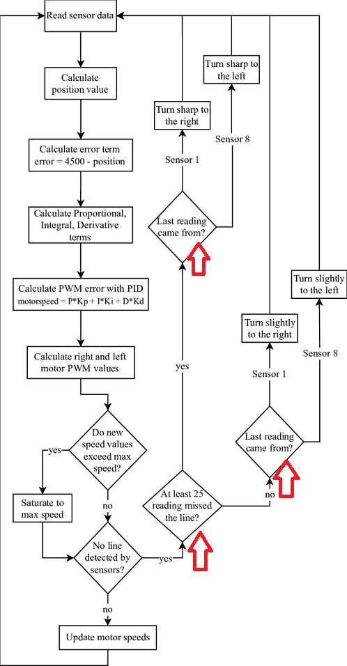
What i want to do are marked in red inside the flow chart
I need to modify my actual code because even if i make a fine tune of Kp,Ki,Kd variables…there will still have too much errors when taking sharp angles…
so i need to solve few problems, unfortunately, my knowledge with programing is limited.
Does anyone can help with:
1- write a code to check if the robot still detect the black line
2- how to check since how long the robot had missed the line? so i can make it turn accordingly
3- Checking which one between far right and far left sensors saw the line the last( to know the right direction where to turn)
4-Using PID…if the error is 0…, the speed is limited to the base speed…Is there any kind of function which accelerate the robot when the error is null ( the robot is centered) and slow it down when negotiating the turns?
Thank you for your precious help.
Here is the actual code i uploaded inside my robot
#include<DRV8835MotorShield.h>
#include<QTRSensors.h>

void CALIBRATE(void);
void CALCULATE_PID(void);
void MOTOR_CONTROL(void);
void DEBUG_POSITION(void);

//QTR sensors
QTRSensors qtr;
const uint8_t SensorCount = 8;
uint16_t sensorValues[SensorCount];

//PID parameter
float Kp = 0.004 , Ki = 40, Kd = 0;
//PID variables
long P, I, D, PID_value, last_error, error = 0, last_I;

//MOTORS
DRV8835MotorShield motors(5,6,3,11);
const float BASE_SPEED = 100, MAX_SPEED = 300, BACKWARD_SPEED = -300; //Max 400
int turn_delay = 0 ; //The time spent ingnoring the sensors
int mode = 2;

void setup()
{
  delay(1000);
  Serial.begin(9600);

//  motors.flipM1(true);
//  motors.flipM2(true);
  pinMode(mode, OUTPUT);
  digitalWrite(mode, HIGH);
  CALIBRATE();
  delay(1000);
}

void loop()
{
  CALCULATE_PID();

//  MOTOR_CONTROL();

  DEBUG_POSITION();
}

void CALCULATE_PID(void){

  error = (qtr.readLineBlack(sensorValues)) - (3500);

  P = error;
  I = I + error;
  D = error - last_error;

  PID_value = (Kp*P) + (Ki*I) + (Kd*D);
  last_I = I;
  last_error = error;

  if(true/*DEBUG*/){
    Serial.print(PID_value);
//    Serial.print(error);
//    Serial.println();
  }
}

void MOTOR_CONTROL(void){
    //Motor speed
    int M1Speed = BASE_SPEED - PID_value;
    int M2Speed = BASE_SPEED + PID_value;
    M1Speed  = constrain(M1Speed, BACKWARD_SPEED, MAX_SPEED);
    M2Speed  = constrain(M2Speed, BACKWARD_SPEED, MAX_SPEED);
    motors.setM1Speed(M1Speed);
    motors.setM2Speed(M2Speed);

  if(false/*DEBUG*/){
    Serial.print("left:");
    Serial.print(M1Speed);
    Serial.print("  ");
    Serial.print("right:");
    Serial.print(M2Speed);
    Serial.println();
  }
  delay(turn_delay);
}

void CALIBRATE(void){
    // configure the sensors
  qtr.setTypeRC();
  qtr.setSensorPins((const uint8_t[]){14, 4, 7, 8, 9, 10, 12, 15}, SensorCount);
  qtr.setEmitterPin(13);

  delay(500);
  pinMode(LED_BUILTIN, OUTPUT);

  digitalWrite(LED_BUILTIN, HIGH); // turn on Arduino's LED to indicate we are in calibration mode
  for (uint16_t i = 0; i < 200; i++)
  {
    qtr.calibrate();
  }
  digitalWrite(LED_BUILTIN, LOW); // turn off Arduino's LED to indicate we are through with calibration

  if(true/*DEBUG*/){
    // print the calibration minimum values measured when emitters were on
    for (uint8_t i = 0; i < SensorCount; i++)
    {
      Serial.print(qtr.calibrationOn.minimum[i]);
      Serial.print(' ');
    }
    Serial.println();

    // print the calibration maximum values measured when emitters were on
    for (uint8_t i = 0; i < SensorCount; i++)
    {
      Serial.print(qtr.calibrationOn.maximum[i]);
      Serial.print(' ');
    }
    Serial.println();
    Serial.println();
  }
}

void DEBUG_POSITION(){
  // read calibrated sensor values and obtain a measure of the line position
  // from 0 to 5000 (for a white line, use readLineWhite() instead)
  uint16_t position = qtr.readLineBlack(sensorValues);

  // print the sensor values as numbers from 0 to 1000, where 0 means maximum
  // reflectance and 1000 means minimum reflectance, followed by the line
  // position
  for (uint8_t i = 0; i < SensorCount; i++)
  {
    Serial.print(sensorValues[i]);
    Serial.print('\t');
  }
  Serial.println(position);

}