Help with adding Header Files

I’m wondering if someone could help me.
I am trying to create code using Eclipse and the wixel SDK, as instructed on the Pololu Wixel User’s Guide PDF.

Being a complete beginner I familiarised myself with the ‘Wireless Serial App’ and ‘Test_Servos’ app.

I wanted to merge parts of the Test_Servos app into the ‘Wireless Serial App’, so that a Wixel located on my robot is able to receive data from another wixel plugged into a PC and is then able to controll some servos on the robot.

However, there was a conflict between the Timer 1 interrupt used by <servo.h> in the Test_Servos app and the Timer 1 interrupt used by <uart1.h> in the Wireless Serial app, so I carefully removed all the UART code from the ‘Wireless Serial App’ and removed the header file. So far so good*.

However, when I add the #include <servo.h> header file into the Wireless Serial app and Build All, I get this message:

**** Build of configuration Default for project wixel-sdk ****

make all
Compiling apps/wireless_serial/wireless_serial.rel
Linking apps/wireless_serial/wireless_serial.hex

?ASlink-Warning-Undefined Global ‘_ISR_T1’ referenced by module 'wireless_serial’
make: *** [apps/wireless_servo/wireless_serial.hex] Error 1

**** Build Finished ****

I’m pretty sure that it is not an issue with timers and interrupts conflicting anymore, as the <radio_com.h> used by the Wireless Serial app uses a the RF general interrupt, and the <servo.h> used a Timer 1 interrupt, but I can’t for the life of me figure out why including the <servo.h> header file into Wireless Serial app won’t work.

I’m worried it’s an obvious answer, but I’m completely clueless about programming!

Many thanks for your help,

Mike

*Upon reflection, I’m not entirely sure if this was necessary, but I wanted to reduce the size of code anyway.

Hello, Mike.

The UART library does not use any timers so there should be no conflict. Did you add an options.mk file to your app to tell it to link to servo.lib?

–David

Hi David,

Many thanks for your reply- it sorted my problem and I was able to complile with no linking errors. However, another problem has come up.

I merged myServosInit() and updateServos() into the Wireless_Serial App, and it went well- My Radio-receiving Wixel is able to initialise the servos (I know it does because my servo starts to hum, and I also set the red LED to turn on when it falls into the ‘initiate’ function).

The wixel is also able to update servo position from the data I send to it via radio (again, I know it jumps into this function because I coded the LED to turn on)
However, the servo is not rotating. It twitches slightly, but no smooth movement. It has a slightly bigger twitch when I switch from a small to a large number being sent through the radio, but no luck.

My guess (and I really don’t know what I’m talking about) is that the T1 interrupt, used by the Servo functions (which, I guess the microchip would be focussing on for most of its time), is being messed up by the RF general interrupt used by the radio transiever. I would imagine this could be messing with the T1 timings and causing the servo to twitch and buzz, rather than rotate.

I’m trying to read up on changing interrupt priority, but I’m not making much sense of it. Is there a way to prioritize the T1 interrupt, or disable the RF interrupt while it is in the servo function?

Sorry for asking all this,

Mike

I

In the source code of the servo library, you can find the code that sets the interrupt priority:

    // Set the Timer 1 interrupt priority to 2, the second highest.
    IP0 &= ~(1<<1);
    IP1 |= (1<<1);

Those registers are documented in the CC2511 datasheet.

Do you have an oscilloscope so you can look at the signal generated by the Wixel? Have you verified independently that your servo works? How are you powering the servo? You could also simplify your code as much as possible and post it here, and I might be able to see a problem.

–David

Having stared at the code for hours and Wikipediaing myself with c code operators, am I correct in thinking the way I should tweak the settings for T1 interrupt priority to the highest is with this:

// Set the Timer 1 interrupt priority to 2, the second highest.
IP0 &= (1<<1);
IP1 |= (1<<1);

This would set the group 3 bits high, according to table 41 in the chip worksheet?

This is exciting stuff!

The line where you are trying to set a bit in IP0 is wrong; you should use “|=”. Once you make that change, then yes, the code should set T1 to be the highest priority.

–David

David, many thanks for your help. It turned out it wasn’t the interrupt priorities after all. I went back to the original Wireless_Serial app and completely stripped it of unnecessary code, including anything to do with the arduino pins and the ioRxSignals functions. I never did know what they were for.

Anyway, after all that, it works! I now have:

PC <-> USB to Wixel <–Radio --> Wixel -> Servomotors

I am a teacher in a school in the UK, and making a remote controlled car is my next year’s project for the kids. Now that I know it works, I’m going to buy £300 worth of Wixels ready for next year.

Many many thanks,

I love wixels!

Mike

Hi David again,

So, my project is going well, but I have hit another snag.
I have managed to get this so far:
Computer <-> Wixel <-> Radio <-> Wixel Onboard Blimp.

The Wixel Onboard Blimp uses a program I have hacked together from combining wireless_serial and test_servo programs. It receives an 8-bit number from the radio.

The least significant 5 bits gives the value of either the servo position, or a motor speed. The most significant 3 bits determine what to drive- either the servo motor, or LeftMotorForward, LeftMotorBackwards, RightMotorForward, RightMotorBackwards.

The Wixel powers the servo directly, but to power the motors, it sends the appropriate pulses to the appropriate pins on a Pololu DRV8833DuelMotor H-Bridge. I power this with a 9V battery to give the motors some juice.

Everything works splendidly- the servo moves, and pulses get sent to and go through the H-Bridge to power the motors. Here is the snag: While the servo only needs pulses of length 700-2,500ms on the 19,114ms pulse period, the motors need the full range- 0-19,114ms pulse lengths.

I look in servo.h to find: SERVO_MAX_TARGET_MICROSECONDS 2500 and my heart sinks. This is why I can’t send pulses of any longer length to the H-bridge, and why the servomotor works fine.

I was wondering, is there a quick and easy way to alter the maximum pulse length from 2,500 to 19,114? I do not know the inner workings of servo.h, or whether this max length is a necessity or can be modified.

Any advice would be gratefully receive- I think this may be my last hurdle!

Many thanks,

Mike

Hello, Mike.

I am glad you are making progress.

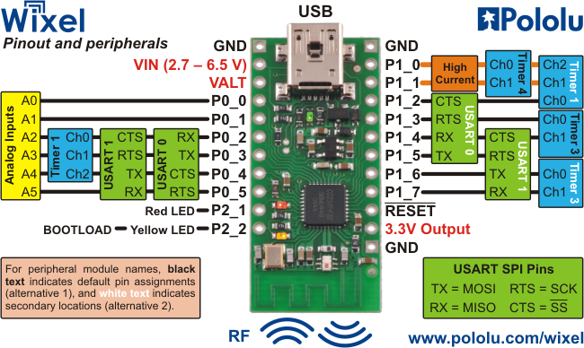
No, there is no quick and easy way to modify the Wixel servo library to allow PWM duty cycles up to 100%. I would recommend leaving the servo library in charge of Timer 1 and configuring Timer 3 to provide PWM for your motor. As you can see below, in this picture from the user’s guide, Timer 3 has two PWM outputs and they can be put in two different locations:

How many servos do you have? If you only have one servo and only need two PWMs for the motors, you might be able to user Timer 1 for everything but then you won’t be able to get supersonic PWM frequencies for the motor.

Also, a 9V battery is a poor choice for powering motors because it can not provide very much current. You could try one or two LiPo cells, or NiMH batteries.

Timer 4 is used by getMs(), but if you start running out of PWMs you could probably configure it to give you two more.

I would love to hear more about the Wixel blimp and see some pictures once it is working!

–David

Hi David,

Some success and one final sticking point :sunglasses:

Using inspiration from a Pololu forum post about PWM and your suggestion, I leant what banks to set and how to code a PWM function using Timer 3.

So far, I have an opperational servomotor (using a cannibalised test_servo code), and my PWM code controlling one motor. The DRV8833 Pololu motor driver requires 2 pins to drive one motor- one having a PWM input and the other being set low. To drive the motor the other way you put the PWM on the other channel. I have used Wixel pins P1_3 and P1_4 for the Left motor.

For my Right motor I would like to use P1_6 and P1_7, and I thought it was a simple case of extending my PWM code to cover these pins to drive the right motor, but as my code stands, there is no PWM being sent from the Wixel to the right motor

Here is my Initialisation code and PWM ISR code. The PWM ISR code has these inputs, which are processed from whattever 8-bit number I send accross the radio: Ldirection and Rdirection- these are bits - 0 for left and 1 for right. Lpulse and Rpulse are numbers 0-31 which determine the speed of the motor.

At the beginning of a PWM cycle, i.e. if(pwmCounter ==32), the appropriate pins are set high and pwmCounter is reset. pwmCounter then ticks up untill either the left or right pulse is due to end e.g. if (pwmCounter == LPulse), then the corresponding pin is set low. I think it’s a simple code, and while it works for Lmotor, it doesn’t for Rmotor.

void PWMinit()
{
	T3IE = 1;			         //Timer3 Interrupt Enable
	T3CTL = 0b10111010;	        //Timer3 Control bits
	T3CC0 = 75;			//Timer3 Capture/Compare value. 
                                                //Calls the interrupt
	T3CCTL0 = 0x24;		        //More T3 setting bits
	P1DIR |= (1<<3);	                //Set P1_3 as output, Lmotor
	P1DIR |= (1<<4);	                //Set P1_4 as output, Lmotor
	P1DIR |= (1<<6);	               //Set P1_6 as output, Rmotor
	P1DIR |= (1<<7);	               //Set P1_7 as output, Rmotor
	IP1   &= (1<<3);	               //SetTimer3 to be low priority- 
                                               //servo is more important!
	IP0   |= (1<<3);	               //
}

ISR(T3,2)
{
	pwmCounter++;					//Timer tick forwards...
	if(pwmCounter == 32)			        //At end of pwm...
	{
		if (LPulse ==0)				//If LPulse=0, no pulse
		{
			P1_3=0;
			P1_4=0;
		}
		if (RPulse ==0)				//If RPulse=0, no pulse
		{
			P1_6=0;
			P1_7=0;
		}
		if (Ldirection == 0 && LPulse !=0)	//If we have a Lforward command...
		{
			P1_3 =1;				//Set P1_3 pin high
			P1_4 =0;				//Set P1_4 pin low
		}
		if (Ldirection == 1 && LPulse !=0)	//If we have a Lbackward command...
		{
			P1_3=0;				//Set P1_3 pin low
			P1_4=1;				//Set P1_4 pin high
		}
		if(Rdirection == 0 && RPulse !=0)	//If we have a Rforward command...
		{
			P1_6=1;
			P1_7=0;
		}
		if(Rdirection == 1 && RPulse !=0)	//If we have a Rbackward command...
		{
			P1_6=0;
			P1_7=0;
		}
		pwmCounter =0;				//Reset tick, let new cycle commence!
	}
	if (pwmCounter == LPulse)			//Time to end LPulse
	{
		P1_3 =0;
		P1_4 =0;
	}
	if (pwmCounter == RPulse)			//Time to end RPulse
	{
		P1_6=0;
		P1_7=0;
	}
}

Do you think it could be due to Timer 3 channels or ‘Alternative Locations’? I can’t see why the ISR needs special permission to use P1_6 and P1_7… I’m just guessing again.

Once this problem is sorted I recon I will have the complete code, then I will build the blimp and fit the electronics to it, and I will give you the complete code and videos of it in action!

Mike

Hello.

I am glad you are making more progress!

Since you are doing software PWM, you can actually choose any pins; you are not limited to the pins you picked which happen to be Timer 3 channels. (However, if you wanted to do hardware PWM, you would be limited to those pins and you could only get two channels at a time.)

I suspect one of the pins you are trying to use might be configured as a hardware PWM pin because of the bits you set in T3CCTL0, so your ISR won’t be able to control it. Try commenting out the line that writes to T3CCTL0.

By the way, this line does not do what you think it does:

IP1 &= (1<<3);  // clears most of the bits in IP1

It should be:

IP1 &= ~(1<<3);  // clear bit 3 in IP1

–David

Hi David,

All done. Commenting out the ‘set hardware PWM’ line did the trick, and everything is now perfect. I can put the Wixels to one side and plan the Blimp’s frame now. I am really gratefull for your help and patience, particularly replying on a Saturday night!

In a week or so, once made, I will upload a video of the Blimp and the code I have cannabilized/ copied/ created to control it.

Many many thanks, untill then,

Mike