I was wondering if I could get some guidance on how to connect the MC33926 motor driver (NOT dual) https://www.pololu.com/product/1212 (please excuse the US version of this site) with the Mini Maestro 12 please?
I understand that the Mini Maestro has a PWM output channel, would I use this to connect to it?
The connections for that driver are explained under the “Pinout” and “Basic Application Connections” sections of its product page. To control PWM with the Maestro, you can connect the appropriate channel to one of the PWM/D inputs on the MC33926. The PWM output is described under the “PWM Output” section of the Maestro’s user’s guide, which can be found under the “Resources” tab of its product page.
If there is something specific that you do not understand about those connections after reading that information, let me know and I will see if I can clarify.
You can control the MC33926 driver with five logic signals from the Maestro, with one of them being the PWM line. However, if you do not need to get current feedback and monitor the errors from the driver, you could use only three signals.
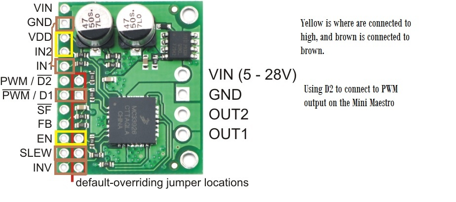
The default-overriding jumpers refer to the row of header pin holes (highlighted in red in this picture) beside the driver’s control pins. These provide a convenient source of either VDD or GND that can be used to enable the pins next to them. These pins are not connected by default. If you have soldered in all of the male headers that come with the driver, you can connect them to their corresponding control pins by adding something like a shorting block or one of our F-F premium jumper wires.
For example, the D1 pin’s default state is HIGH. So, if you soldered in all of the male headers and added a shorting block between D1 and the pin to the right of it (which is GND), D1’s state becomes LOW, which stops it from disabling the driver’s outputs. The table on the Pinout section of the product page lists the default state for each pin.
You mentioned that IN1 was set to LOW, but then later mentioned that IN1 was set HIGH. If IN1 and IN2 are both set to LOW or both set to HIGH, then the motor will be commanded to brake. Also, the SF pin should not be driven high; it should be monitored as an input in case it ever latches LOW during a fault. If you do not need to read the fault, you can leave it disconnected.
If you fix those logic connections and still do not get the motor to turn, can you tell me more about your setup? What kind of motor are you using? What is its stall current and intended operating voltage? How are you powering your motor?
Can you also post your Maestro settings file, and a picture of your connections?
Here is a [crude] picture of how I have connected the MC33926 up. I am powering it using a 5v, 4A power supply which is strong enough to run my 6 servos (though I tried testing the MC33926 without the servos)
Also, I would prefer is INV and SLEW were grounded, but I have run out of grounds on the MC33926, can I use the grounds from the Mini Maestro? I am not sure if they would be common.
I am not entirely sure, but based on what you have said and shown in your figure it sounds like you are not supplying logic power (5V) to VDD. With VDD not connected, the default overriding jumpers that are intended to connect a neighboring pin to logic HIGH will not actually be supplying that voltage.
In general, you should connect the grounds of all of your devices together. So the Maestro and MC33926 carrier should share a ground. As for actually making those connections, you might consider using something like our solderless breadboard and premium jumper wires to make ground easier to connect to.
Also, the motor supply voltage you mentioned you are using is right at the threshold that the MC33926 can operate at, so it might not work consistently if that voltage dips. I recommend getting a 6V supply to be safe. You might consider sharing that supply for your servos, if they can tolerate those voltages.