HELP, are inrush surges killing my U3V50F24s?

After years of good service, I’m seeing failures (4 out of 76) when I first connect a +18V Li Battery to one of my Pololu 24V Step-Up Voltage Regulators (U3V50F24). In my applications this booster charges-up a capacitor bank of 4000 uFd that powers a 20 Ohm solenoid, switched ON for 1.2 seconds once every day. On startup failure it blows a 3 Amp fuse in series with the LiBatt.

What is the maximum capacitance load rating of Pololu 24V Step-Up Voltage Regulators (U3V50F24)? Does it have soft start?

Can I protect my U3V50F24 against inrush surges by adding a 10 Ohm resistor in series with its output? Or, is there a better +24V booster that has soft start?

Hello.

Thank you for using our regulators over the past several years, and I am sorry to hear you are seeing failures with some of them. Can you clarify how much use the problematic units saw before failing as well as how long you have used other units of this regulator for this application in general?

Can you post some scope captures that show what is going on? Also, are the boards failing when you connect the power supply or the load, and how is that supply/load being connected?

We have not characterized the maximum capacitance load these regulators can handle in detail, but they do have a soft start feature. We do not have any similarly powerful step-up regulators that output 24V.

- Patrick

Hello Patrick,

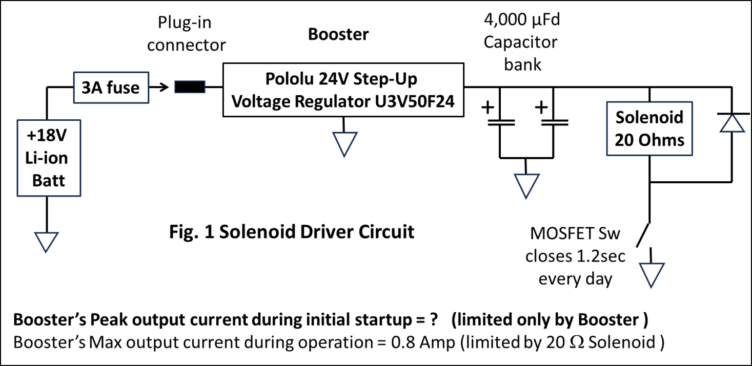
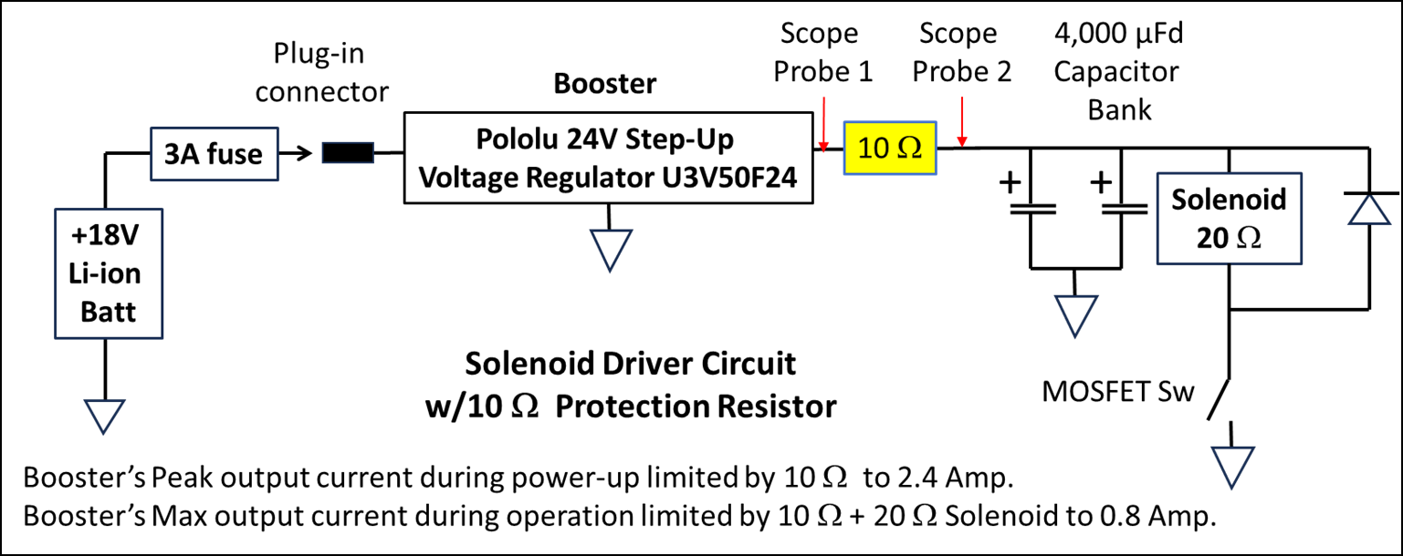
Thank you for your prompt response to our 24V Step-Up Regulators (U3V50F24) problems. We call them 24V Boosters that we use in our Solenoid Driver Circuit, shown below in Fig 1.

First to answer your questions: “… how much use the problematic units saw before failing as well as how long you have used other units of this regulator for this application in general? “

As part of our ongoing equipment upgrade, we started installing these 24V Boosters beginning in March of this year. To date, we’ve installed 70 Boosters, with five experiencing premature failures after their first trouble-free weeks/months of operation. There were no failures during R&D and manufacturing testing and there were no failures during the first few weeks of operations with many ON/OFF cycles. Currently, we have 65 units running 24/7 with Boosters and we would like to add many more. Therefore, we would appreciate your help to improve our Booster applications.

Our application is illustrated in Fig 1. To start, the +18V Li-Batt is manually plugged into the Vin of the Booster. It charges-up the 4,000 μFd capacitor bank that is directly connected to Vout. Initially, the Solenoid’s MOSFET Sw is OFF and once every day it is turned ON for 1.2 seconds by a microcontroller (not shown). Operations continue 24/7, typically for a month, after which it’s unplugged, maintenance and testing is performed, and then it’s returned to service.

Failures: The five failed Boosters had been working successfully 24/7 during a wide range of weeks and months with many plug/unplug cycles. Typically, the failures occurred immediately when power was again applied to a Booster that had an uncharged capacitor bank load. During start-up the Booster’s peak input and output currents are limited only by the Booster itself. We suspect that damaging start-up transients may cause the Booster to draw excessive current that blows the 3 Amp fuse. We also suspect startup transients may be damaging new Boosters causing them to fail prematurely.

Analysis: So far, I received and tested four of the five failed Boosters. Each failed Boosters’ Vin was opened circuited to GND. Booster #4’s Vout reads 4.6W and the three remaining Boosters Vout’s read less than 1W to GND. (Multimeter test probes +/- & -/+ and wait for steady state).

During initial start with an uncharged capacitor bank, the Booster’s inrush current is limited only by the Booster itself plus what little resistance there is in the wiring and fuse to the +18V supply.

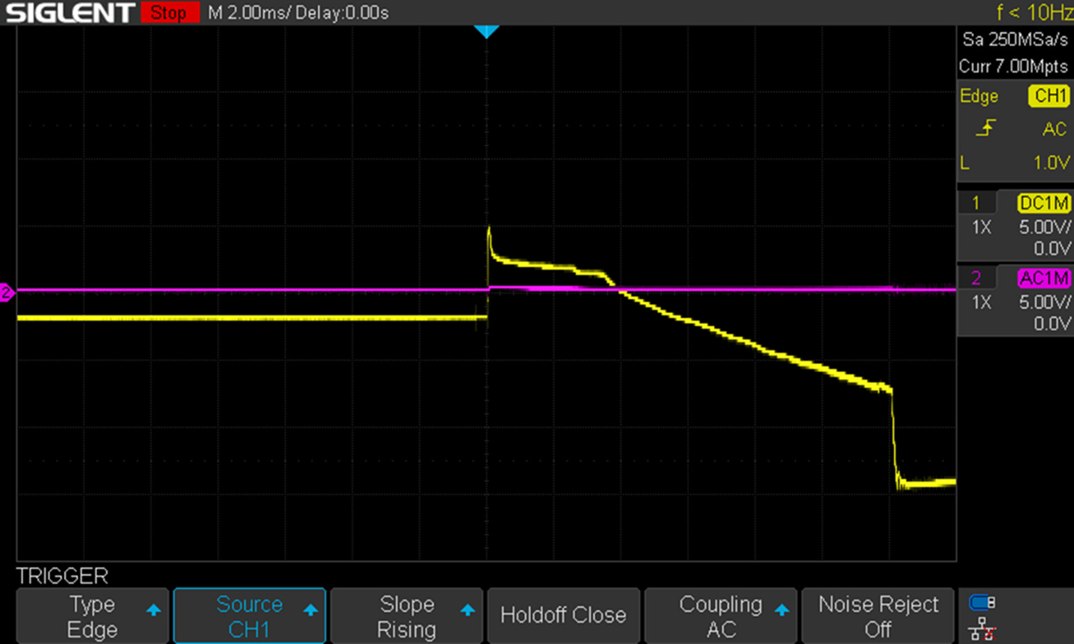
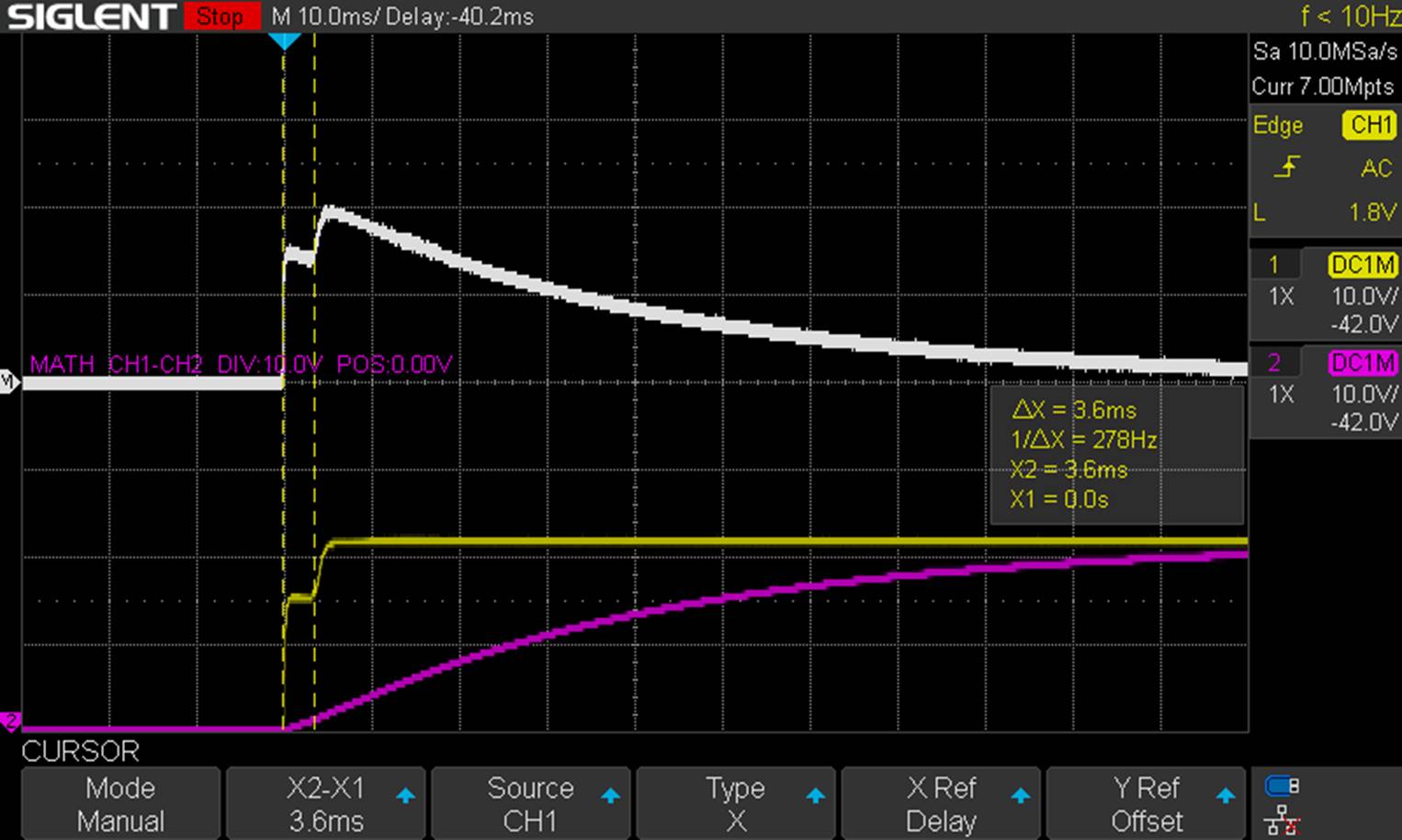
I managed to capture the following Scope photo of a Booster’s Vin startup transient. The yellow trace is Vin (Chan 1) and the purple trace is Vout (Chan 2). Unfortunately, I couldn’t capture my chief suspect, the inrush current, with the equipment I have. The sharp voltage transient at Vin of over +10V then down to about -25 at Vin is surprising since its wired directly to the +18V Li-Batt through the manual plug-in connector and 3A fuse. The steady Vout was not surprising since it is connected to the low ESR 4000 μFd capacitor bank. Sorry the reticule scale didn’t print out.

Scope Photo 1: Start-up transient at Booster’s Vin and Vout

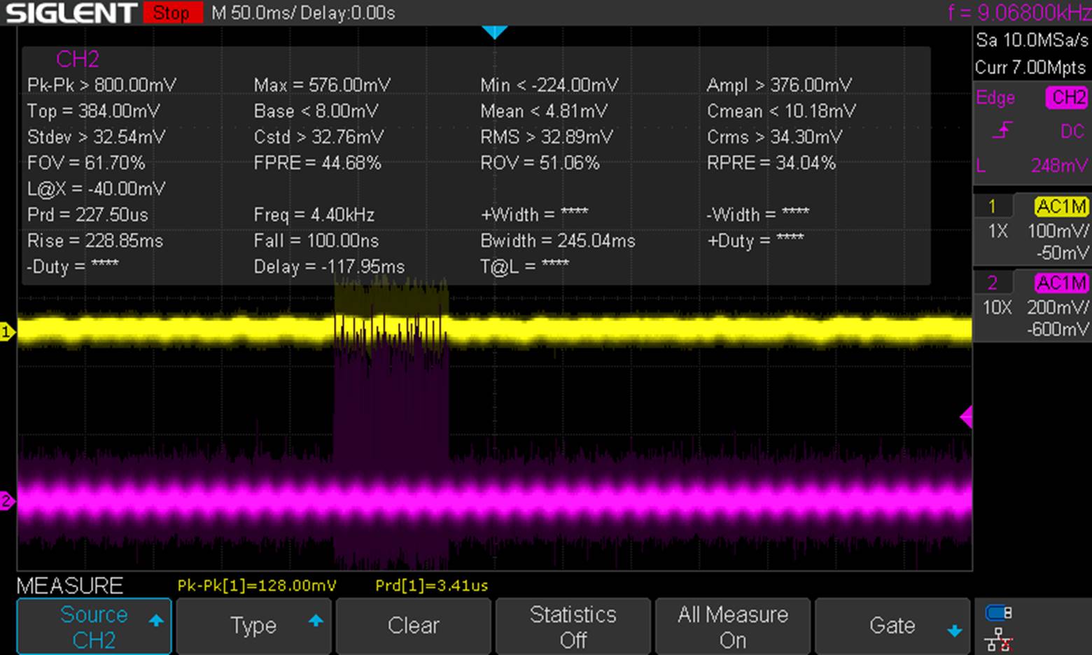
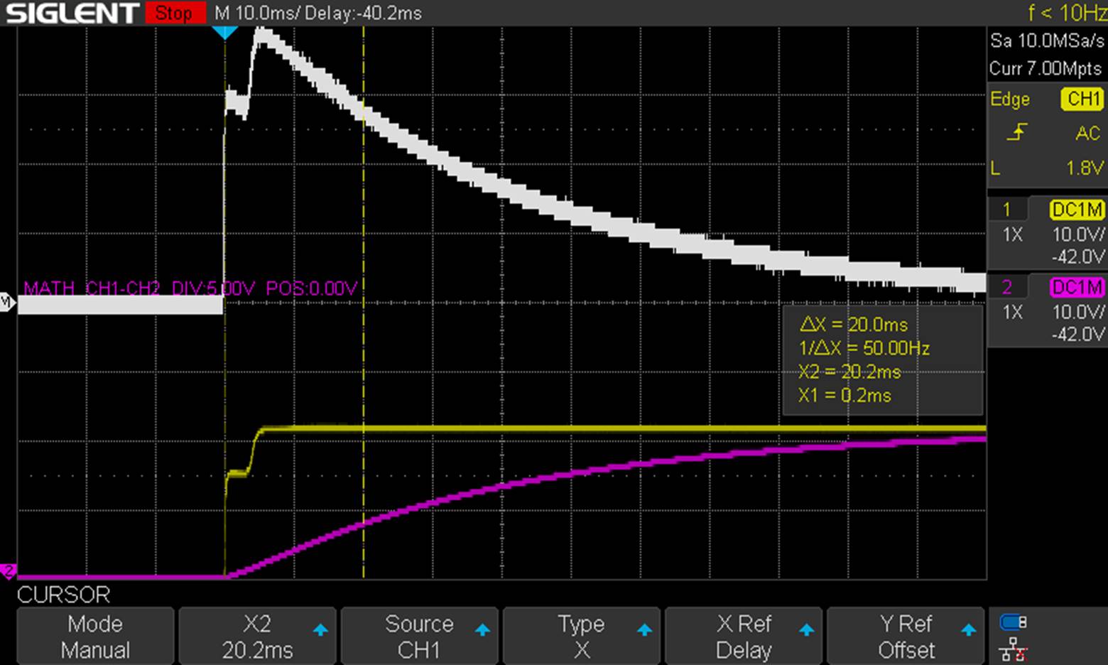
After the Booster survived this abrupt start, it charged the capacitor bank up to +24V and continued running with no-load as shown in Scope Photo 2 below.

Scope Photo 2: Booster running normally at no load with +18Vin and +24V output

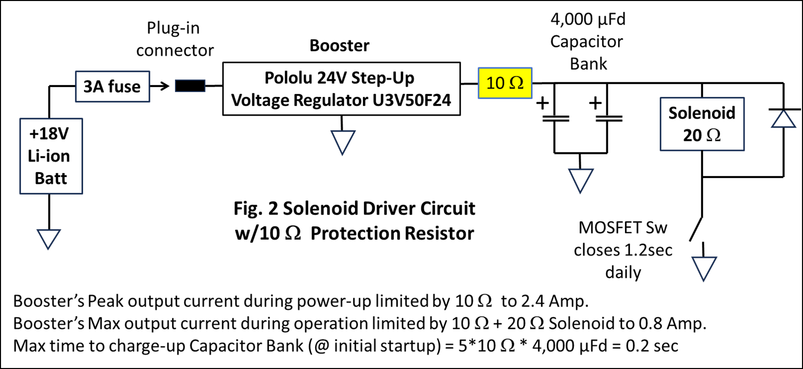
Next step: To limit the Booster’s capacitor bank start-up load we’re going to test adding a 10 W resistor in series with the Booster’s output as shown below.

We really like your +24V Step-Up Regulators (U3V50F24) but are concerned we are misusing it because we don’t know its in-rush current and capacitive load limitations.

Therefore we would appreciate your advice.

Best regards,

Tony

Thanks for the additional information and scope captures. It is plausible that your boards are being damaged by a voltage spike caused by inrush current into the capacitor bank, and if that is the issue, then adding a 10Ω resistor inline with the output might solve it.

The first scope capture you posted seems pretty unusual. Maybe your scope probe is not properly grounded or is calibrated poorly, so I recommend checking for those issues before anymore troubleshooting. From there, if you want to validate that this is a current inrush issue, I suggest you look at the regulator’s turn-on behavior at the input and output without any load attached to use that as a base line for comparison when you add back the capacitor bank and the resistor load. If possible, it might be interesting to break up the capacitor bank and add it back in stages while looking at it with your scope.

If you continue having trouble, can you post more scope captures from your investigation (including ones that show how the 10Ω changes the turn-on behavior) along with some pictures of your physical setup and the damaged units? It might also be a good idea to look at a few units to confirm the behavior is consistent, especially if you keep seeing strange behavior like in your first scope capture.

Also, for future reference, it seems like you used “W” in several places in your post to indicate ohms, which is confusing since W is usually used as an abbreviation for Watts. Using the symbol for capital omega, Ω, or writing out ohms would be clearer.

- Patrick

Hi Patrick,

Thanks for your prompt and excellent advice.

I will follow up as you recommend.

  • Tony

Hi Patrick,

Thanks again for your prompt and instructive advice.

Here’s the results of my latest test to evaluate the effectiveness of the 10 Ohm resistor to limit destructive in-rush surges.

We suspect these in-rush surges are causing premature failures of the 24Volt Step-up Voltage Regulator (aka Booster) in the Solenoid Driver circuit shown below.

The following oscilloscope traces show the Booster’s output transient during power up from an 18 Volt Li-ion Battery.

The capacitor bank was fully discharged and the Solenoid switch remained OFF.

The yellow trace 1 shows the Booster’s Vout to GND (scope: 10V/Div & 10ms/Div).

The purple trace 2 shows the Capacitor’s Voltage to GND (scope: 10V/Div & 10ms/Div).

The white trace shows the voltage difference across the 10 Ohm resistor. Equivalently, this also shows the Booster’s output current (1 Amp/Div) since the scale is set to 10V/Div across the 10 Ohm resistor.

Test results: initially, the Booster’s output voltage steps-up, first to about 16V with 1.6 Amp out for 3.6 ms followed by its ramping up to its regulated 24V in about 5ms. Its peak output current at start-up was about 2 Amp that exponentially decays as the capacitor bank charges up. The time constant of that decay is consistent with a low impedance Booster feeding the 10 Ohm resistor in series with the 4,000uFd capacitor bank. That time constant is R*C = 40 ms. The purple trace shows the capacitor bank reaches about ½ of its final value of 24 Volts in 28 ms, as expected for an RC circuit charging to 24 Volts (image.png).

The following scope trace shows the Booster’s output current on a larger scale of 5Amp/Div.

The Booster’s peak output current exhibits a first step to 1.5 Amp in a few ms then barely reaches 2 Amps after which it decays to zero with the same 40 ms time constant as the capacitor’s charging time.

The 10 Ohm resistor provided sufficient load to limit the Booster output to 2 Amps, which is within its 5 Amp specification and the 3 Amp fuse’s rating.

Regards,

Tony

Hello, Tony.

Thanks for the update sharing the details and scope captures from your investigation! The results seem promising.

- Patrick