
Bought a used car with 2 dc motors have a mega 2560 board, infrared sensor, L9110S motor driver controller board seem I thought I was able to do this need a schematic.(9volt)
Hello.
I am not sure what you are asking for. Can you clarify your question?
-Derrill
I need a proper schematic that’s all or a proper sketch
A schematic or sketch for what?
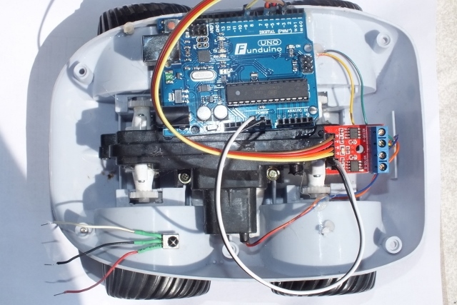
Hi this is what I am up to if anyone has a schematic or similar project please submit.
Been done a million times. Spend some more time with your buddy Google.
Ok Jim be a buddy and supply me a diagram or sketch. It may of been done a million times but it’s a first for me. Or supply a link that shows this kind of project.
This datasheet for the L9110 may help: nvhs.files.wordpress.com/2013/02 … -l9110.pdf
Look at the bottom at the application schematic. So you tie the dc motor to OA and OB. Forward signal is, as I understand it, IA and IB. Now you have to figure out how that corresponds to your motor controller board’s pins.
Next, is 800mA sufficient for continuous current on these particular motors? You may have to actually measure with a DMM as I doubt you can find a datasheet for them. They are likely way too generic for that.
After you verify that you’re not going to burn up your controller board, then you can interface the Arduino with the controller board and motor. Then it’s time to write a sketch to turn on the correct pins at the correct time to get the controller board to turn on the motor in the correct direction.
After that you can start thinking about PWM, sensors, etc.