Gyro - Accelerometer jumps!

Good day!

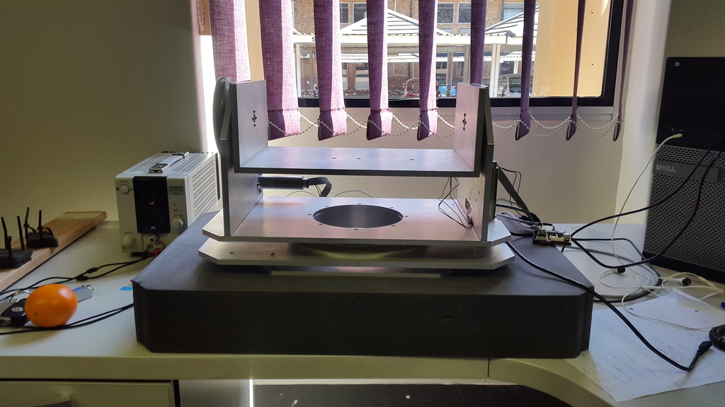
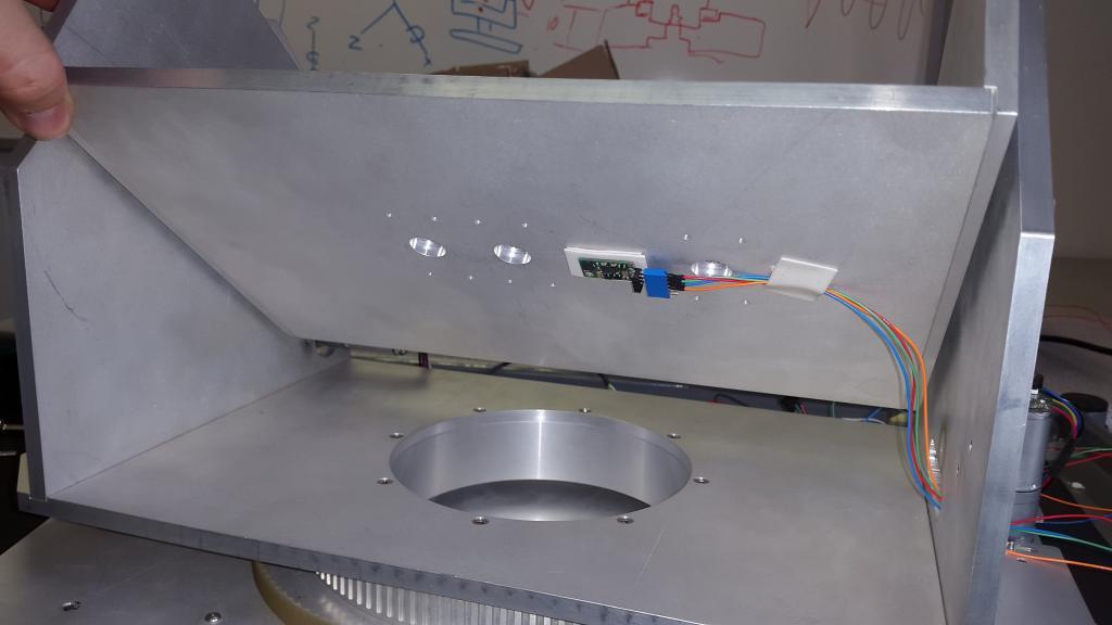
I am using an MiniIMU9 v2 as a measuring unit to stabilize my Pan and Tilt platform. I am currently trying to stabilize the Tilt Platform by using the gyro sensor for the stability purposes and the accelerometer to prevent gyro drift as well as platform position accuracy.

My problem: as soon as I add either the gyro or accelerometer output readings to the Tilt PID control calculations, the platform jumps occasionally very violently ( I assume it is because of gyro noise that causes an output in which the motors then rotates, where as the accelerometer then reads and tries to compensate for this, then the gyro receives a reading that the accelerometer then creates and then tries to compensate for…thus the 2 sensors are working against each other). If I only use the gyro sensor, the platform does not jump but I end up with gyro drift and an inaccurate platform position. With the accelerometer only, the platform does not jump as well and it seems pretty accurate, but then I’ll only end up with a “pendulum-effect” platform instead of a platform that is stable via the gyro sensor. How do I use both sensors without the platform jumping so much? Please find my code below. (excuse the amount of commented code, I have been using this code for a while) Please help me create some peace between my 2 sensors! Any suggestions would be helpful!

[code]#include <PID_v1.h> // library for PID Controller
#include <Wire.h>
#include <L3G.h> // library for Gryro sensors
#include <LSM303.h> // library for Accelerometer and Magnetometer sensors

int PIN_DIRECTION_0 = 5; // Direction Pin for Motor 1
int PIN_ENABLE_0 = 6; //Enable Pin for Motor 1
int PIN_PWM_0 = 2; //PWM Pin for Motor 1
int PIN_DIRECTION_1 = 11; // Direction Pin for Motor 2
int PIN_ENABLE_1 = 10; //Enable Pin for Motor 2
int PIN_PWM_1 = 8; //PWM Pin for Motor 2

LSM303 compass;
L3G gyro;
String MyVar("");

//----------------------------------------------------------------//
double SetpointT, InputT, OutputT; //Define Variables we’ll be connecting to
double KpT=1.0, KiT=0.0, KdT=0.0;
PID myPIDT (&InputT, &OutputT, &SetpointT,KpT,KiT,KdT, DIRECT); //Specify the links and initial tuning parameters for the TILT axis
//----------------------------------------------------------------//
double SetpointP, InputP, OutputP;
//double KpP=3.0, KiP=1.0, KdP=0.0;
double KpP=1.0, KiP=0.0, KdP=0.0;
PID myPIDP (&InputP, &OutputP, &SetpointP,KpP,KiP,KdP, DIRECT); //Specify the links and initial tuning parameters for the PAN axis
//----------------------------------------------------------------//

//int setspeedPAN;
//int setspeedTILT;

//float MAG_setpoint;
//float current_MAG_reading;
//double MAG_Kp = -0.5;
//double MAG_Ki = 0.00;

#define RAD_to_DEG 57.295779513082320876798154814105
float accXangle = 0;
float R = 0;
//float Sigma = 0;

const int sampleRate = 1; //Variable that determines how fast the PID loop will run

void updatevars()
{
int rchar; // = Serial.read();

if (Serial.available() > 0) 
{
  rchar = Serial.read();

  if(rchar == 'p')
  {
    KpT = MyVar.toInt();
    myPIDT.SetTunings(KpT, KiT, KdT);
    Serial.print("Kp Tilt=");
    Serial.println(KpT);
    MyVar = "";
  }
  else if(rchar == 'i')
  {
    KiT = MyVar.toInt();
    myPIDT.SetTunings(KpT, KiT, KdT);
    Serial.print("Ki Tilt=");
    Serial.println(KiT);
    MyVar = "";
  }
  else if(rchar == 'd')
  {
    KdT = (MyVar.toInt()/100.0);
    myPIDT.SetTunings(KpT, KiT, KdT);
    Serial.print("Kd Tilt=");
    Serial.println(KdT);
    MyVar = "";
  }
 else if(rchar == 'a')
 {
    KpP = MyVar.toInt();
    myPIDP.SetTunings(KpP, KiP, KdP);
    Serial.print("Kp Pan=");
    Serial.println(KpP);
    MyVar = "";
  }
  else if(rchar == 'b')
  {
    KiP = MyVar.toInt();
    myPIDP.SetTunings(KpP, KiP, KdP);
    Serial.print("Ki Pan=");
    Serial.println(KiP);
    MyVar = "";
  }
  else if(rchar == 'c')
  {
    KdP = (MyVar.toInt()/100.0);
    myPIDP.SetTunings(KpP, KiP, KdP);
    Serial.print("Kd Pan=");
    Serial.println(KdP);
    MyVar = "";
  }
 
  else
  {
    MyVar += char(rchar);
  }

}
}

void setMspeed(int M, int V1)
{
int direct=0;
int a;

if (V1 < 0)
{
  direct = 1;
  V1 = -V1;
}
if (V1 > 200)
{
  V1 = 200;
}

a = V1 + 26;
if(M == 0)
{
  analogWrite(PIN_PWM_0, a);
  digitalWrite(PIN_DIRECTION_0, direct);
}
else
{
  analogWrite(PIN_PWM_1, a);
  digitalWrite(PIN_DIRECTION_1, direct);
}

}

void setM1speed(int v)
{
setMspeed(0,v);
}
void setM2speed(int v)
{
setMspeed(1,v);
}

void setup()
{
Serial.begin(115200);
Wire.begin();
compass.init();
compass.enableDefault();

pinMode(PIN_DIRECTION_0, OUTPUT);
pinMode(PIN_ENABLE_0, OUTPUT);
pinMode(PIN_PWM_0, OUTPUT);
digitalWrite(PIN_ENABLE_0, HIGH);
pinMode(PIN_DIRECTION_1, OUTPUT);
pinMode(PIN_ENABLE_1, OUTPUT);
pinMode(PIN_PWM_1, OUTPUT);
digitalWrite(PIN_ENABLE_1, HIGH);

//compass.read();
//R=sqrt(pow(compass.a.x,2)+pow(compass.a.y,2)+pow(compass.a.z,2));
//accXangle = acos(compass.a.y/R)*RAD_to_DEG - 91;

//InputT = ((gyro.g.x/256)-1.6)+(accXangle);
//SetpointT = 0;

//compass.m_min = (LSM303::vector<int16_t>){-362, -270, -194};
//compass.m_max = (LSM303::vector<int16_t>){+155, +415, +350};

//MAG_setpoint = compass.heading(); //Get current position reading from compass
//Sigma = 0.0;

InputP = (((gyro.g.z/256)+0.9)+((gyro.g.y/256)-0.8));
SetpointP = 0;

if (!gyro.init())
{
Serial.println(“Failed to autodetect gyro type!”);
while (1);
}

myPIDT.SetOutputLimits(-200, 200);
myPIDP.SetOutputLimits(-200, 200);

gyro.enableDefault();

myPIDT.SetMode(AUTOMATIC); //Turn on PID - Tilt
myPIDT.SetSampleTime(sampleRate); //Sets the sample rate

myPIDP.SetMode(AUTOMATIC); //Turn on PID - Pan
myPIDP.SetSampleTime(sampleRate); //Sets the sample rate
}

void loop()
{
//float Delta;

gyro.read();

/*loopcounter = loopcounter+1;
if (loopcounter >= 1000)
{
Serial.println(" Loop Complete ");
loopcounter = 0;
}
*/
compass.read();
R=sqrt(pow(compass.a.x,2)+pow(compass.a.y,2)+pow(compass.a.z,2));
accXangle = acos(compass.a.y/R)*RAD_to_DEG - 91;

InputT = (gyro.g.x/256)-1.0 + ((accXangle)/5.0);
SetpointT = 0.0;
myPIDT.Compute();

// current_MAG_reading = compass.heading();
// Delta = ((current_MAG_reading + 360) - (MAG_setpoint))*MAG_Kp; // differentiation of compass.heading; substracts current compass reading with old compass reading
// Delta = Delta >= 360 ? Delta - 360 : Delta;

// Sigma = (Sigma + Delta); //integration of Delta
// Sigma = Sigma >= 100 ? 100 : Sigma <= -100 ? -100 : Sigma;

InputP = (((gyro.g.z/256)+0.9)+((gyro.g.y/256)-0.8));
// InputP = 0.0;
SetpointP = 0.0; //SetpointP = (Sigma *MAG_Ki) + (Delta * MAG_Kp);
myPIDP.Compute();

setM1speed(-OutputT);
setM2speed(-OutputP);

//Serial.print("Input Tilt: “);
//Serial.println(InputT);
/*Serial.print(”\t Output Tilt: “);
Serial.print(OutputT);
Serial.print(”\t Input Pan: “);
Serial.print(InputP);
Serial.print(”\t Output Pan: “);
Serial.print(OutputP);
Serial.print(”\t Magnetometer: ");
Serial.println(current_MAG_reading);

/*
Serial.print("MAG_setpoint: “);
Serial.print(MAG_setpoint);
Serial.print(”\t current_MAG_reading: “);
Serial.print(current_MAG_reading);
Serial.print(”\t Delta: “);
Serial.print(Delta);
Serial.print(”\t Sigma: ");
Serial.println(Sigma);
//*/
// Serial.print("Gyro Pan Value: ");
//Serial.println(PIN_PWM_0);
updatevars();
//Serial.println(InputT);
}[/code]

Kind regards
Vince

As you admit, this code is a mess and extremely difficult to follow. There are also a number of mathematically dubious operations. For example, it is hard to imagine why one would directly add together measurements presumably taken from completely independent axes, along with arbitrary constants:

If you want help, you should take a few moments to describe the theory you want to implement and how the code is supposed to accomplish that. What is the mechanical arrangement of the motors/actuators that are supposed to orient the platform? Keep in mind that the heart of an algorithm to implement a self-stabilizing platform can be written in less than a dozen lines of code.

In the process, please eliminate all the commented out junk so that someone else can hope to follow your reasoning.

Hi Jim,

Thanks for the reply, and sorry about the commented clutter :blush: . I have tidied-up the program and tried to make it more understandable. The objective I am trying to complete is to create a Stabilized Pan and Tilt system that will be mounted on a vehicle that will be moving at ±12 m/s. The platform will be carrying an inspection camera and should be able to aim (and be stable) at a desired view point. Each platform are driven using timing belts and pulleys. The components I’m currently using is as follows:

  1. Adruino Mega ADK
  2. MiniIMU9 v2
  3. 2x DCX 22L Maxon Motors with a 83:1 gearhead and a 256 CPT Quad Encoder - (Part Num: B743AC3C5F43)
  4. Escon 36/2 DC Servo Servo Controller that uses its own Escon Studio program - (Part Num: 403112)

I have added some pictures for your reference if needed. The IMU is mounted under the Tilt platform temporarily.

My program consists of the following:

  1. 2x PID Controllers for each axis respectively
  2. A function that allows me to adjust the PID gain values while the program is running
  3. A function for the motor controller to identify the max and min speed of the motor, which motor to use by Enabling the required pin, and the required motor direction.
  4. The setup loop function
  5. The basic loop function

I’m currently working on the TILT axis only, even-though the program is created for both axis. This way I can adjust the TILT axis and when the desired output is found I can switch over to the PAN axis. So the PAN axis is disconnected for now. The problem I’m experiencing at the moment is as explained previously, and I’m not sure how to resolve this.
Please excuse my programming methods, I’m relatively new.
Thank you again.

[code]#include <PID_v1.h> // library for PID Controller
#include <Wire.h> // I2C Lib
#include <L3G.h> // library for Gryro sensors
#include <LSM303.h> // library for Accelerometer and Magnetometer sensors

int PIN_DIRECTION_0 = 5; // Direction Pin for Motor 1
int PIN_ENABLE_0 = 6; //Enable Pin for Motor 1
int PIN_PWM_0 = 2; //PWM Pin for Motor 1
int PIN_DIRECTION_1 = 11; // Direction Pin for Motor 2
int PIN_ENABLE_1 = 10; //Enable Pin for Motor 2
int PIN_PWM_1 = 8; //PWM Pin for Motor 2

LSM303 compass;
L3G gyro;
String MyVar("");

#define RAD_to_DEG 57.295779513082320876798154814105 //to convert Radians to Degrees
float accYangle = 0;
float R = 0;

//------------------PID CONTROL - TILT----------------------------//
double SetpointT, InputT, OutputT; //Define Variables we’ll be connecting to
double KpT=1.0, KiT=0.0, KdT=0.0;
PID myPIDT (&InputT, &OutputT, &SetpointT,KpT,KiT,KdT, DIRECT); //Specify the links and initial tuning parameters for the TILT axis
//------------------PID CONTROL - PAN-----------------------------//
double SetpointP, InputP, OutputP;
double KpP=1.0, KiP=0.0, KdP=0.0;
PID myPIDP (&InputP, &OutputP, &SetpointP,KpP,KiP,KdP, DIRECT); //Specify the links and initial tuning parameters for the PAN axis
//----------------------------------------------------------------//

const int sampleRate = 1; //Variable that determines how fast the PID loop will run

//----------------------------------------------------------------//
//Function to edit gain value whilst running//
//----------------------------------------------------------------//
void updatevars()
{
int rchar; // = Serial.read();

if (Serial.available() > 0) 
{
  rchar = Serial.read();

  if(rchar == 'p')  // P-Gain for motor 1 (Tilt)
  {
    KpT = MyVar.toInt();
    myPIDT.SetTunings(KpT, KiT, KdT);
    Serial.print("Kp Tilt=");
    Serial.println(KpT);
    MyVar = "";
  }
  else if(rchar == 'i') // I-Gain for motor 1 (Tilt)
  {
    KiT = MyVar.toInt();
    myPIDT.SetTunings(KpT, KiT, KdT);
    Serial.print("Ki Tilt=");
    Serial.println(KiT);
    MyVar = "";
  }
  else if(rchar == 'd') // D-Gain for motor 1 (Tilt)
  {
    KdT = (MyVar.toInt()/100.0);
    myPIDT.SetTunings(KpT, KiT, KdT);
    Serial.print("Kd Tilt=");
    Serial.println(KdT);
    MyVar = "";
  }
 else if(rchar == 'a') // P-Gain for motor 2 (Pan)
 {
    KpP = MyVar.toInt();
    myPIDP.SetTunings(KpP, KiP, KdP);
    Serial.print("Kp Pan=");
    Serial.println(KpP);
    MyVar = "";
  }
  else if(rchar == 'b') // I-Gain for motor 2 (Pan)
  {
    KiP = MyVar.toInt();
    myPIDP.SetTunings(KpP, KiP, KdP);
    Serial.print("Ki Pan=");
    Serial.println(KiP);
    MyVar = "";
  }
  else if(rchar == 'c') // D-Gain for motor 2 (Pan)
  {
    KdP = (MyVar.toInt()/100.0);
    myPIDP.SetTunings(KpP, KiP, KdP);
    Serial.print("Kd Pan=");
    Serial.println(KdP);
    MyVar = "";
  }
 
  else
  {
    MyVar += char(rchar);
  }

}
}

//----------------------------------------------------------------//
//Function to scale motor speed, enable specific motor and set motor direction//
//----------------------------------------------------------------//

void setMspeed(int M, int V1)
{
int direct=0;
int a;

if (V1 < 0)
{
  direct = 1;
  V1 = -V1;
}
if (V1 > 200)
{
  V1 = 200;
}

a = V1 + 26;
if(M == 0)
{
  analogWrite(PIN_PWM_0, a);
  digitalWrite(PIN_DIRECTION_0, direct);
}
else
{
  analogWrite(PIN_PWM_1, a);
  digitalWrite(PIN_DIRECTION_1, direct);
}

}

void setM1speed(int v)
{
setMspeed(0,v);
}
void setM2speed(int v)
{
setMspeed(1,v);
}

//----------------------------------------------------------------//
//Basic Setup Funtion//
//----------------------------------------------------------------//

void setup()
{
Serial.begin(115200);
Wire.begin();
gyro.init();
compass.init();

pinMode(PIN_DIRECTION_0, OUTPUT);
pinMode(PIN_ENABLE_0, OUTPUT);
pinMode(PIN_PWM_0, OUTPUT);
digitalWrite(PIN_ENABLE_0, HIGH);
pinMode(PIN_DIRECTION_1, OUTPUT);
pinMode(PIN_ENABLE_1, OUTPUT);
pinMode(PIN_PWM_1, OUTPUT);
digitalWrite(PIN_ENABLE_1, HIGH);

myPIDT.SetOutputLimits(-200, 200);
myPIDP.SetOutputLimits(-200, 200);

gyro.enableDefault();
compass.enableDefault();

myPIDT.SetMode(AUTOMATIC); //Turn on PID - Tilt
myPIDT.SetSampleTime(sampleRate); //Sets the sample rate

myPIDP.SetMode(AUTOMATIC); //Turn on PID - Pan
myPIDP.SetSampleTime(sampleRate); //Sets the sample rate
}

//----------------------------------------------------------------//
//Basic Loop Function//
//----------------------------------------------------------------//

void loop()
{
gyro.read();
compass.read();

R=sqrt(pow(compass.a.x,2)+pow(compass.a.y,2)+pow(compass.a.z,2));
accYangle = acos(compass.a.y/R)*RAD_to_DEG - 90; //to determine the y-axis angle using the accelerometer

InputT = (((gyro.g.x/256)-1.0)/5.0)+(accYangle); //Input value for Tilt via gyro sensor at x-axis and acclerometer sensor at y-axis
SetpointT = 0.0;
myPIDT.Compute();

InputP = (gyro.g.z/256)+0.9; //Input value for Pan via gyro sensor at z-axis
SetpointP = 0.0;
myPIDP.Compute();

setM1speed(-OutputT);
setM2speed(-OutputP);

updatevars();

}[/code]

You still haven’t described the theory that you are trying to implement, and after glancing through the code, it is not obvious what that might be. The program certainly can’t work as it stands.

In the larger picture, it is not clear that you need the gyro for this application. Its purpose is to override erroneous accelerometer angle measurements when the platform is subjected to sudden rotations. In the absence of a gyro, there are ways of filtering accelerometer measurements to reduce this effect.

If you do need the gyro, you must combine the gyro and compass/accelerometer readings in a way that cancels gyro drift. There is plenty of material on the web explaining how to do this, but most of it is not for beginners. In the long run, a better way to go may be to use an AHRS, like this one github.com/richards-tech/RTIMULib-Arduino

Some details:

  1. Gyros return the rate of rotation, not an angle. So, you have to keep track of time between readings, and accumulate the total angle rotated from the start, e.g. gyro_tilt_y = gyro_tilt_y + gyro.g.x*dt; The variables must be floating point and the gyro readings scaled appropriately.

  2. Gyros have offsets, and drift. After a minute or two, the accumulated angles won’t be consistent with the starting point. You need to determine and subtract the offset, and deal with the drift elsewhere.

  3. Do the angles you calculate from the accelerometer make sense? Print them out. atan2() is better than acos() for this, because you don’t lose the sign information.

  4. This line has several potential, as well as obvious problems:

a. As pointed out above, gyro.g.x is a rotation rate, not an angle.
b. What are the arbitrary constants 1 and 5 supposed to be doing?
c. The compiler may interpret (gyro.g.x/256) as an integer divide, which would be a disaster. Add a decimal point after the 256 to make this a floating point calculation.
d. Combine the gyro angle (not rate) with the accelerometer angular readings elsewhere, to counteract gyro drift.

By the way, you may stumble upon some Kalman filter code, attributed to rotomotion’s “tilt.c”, to combine 1D gyro and accelerometer measurements. It is often used for self-balancing robots; very popular and seems to be everywhere, but it was not implemented correctly (not even in theory) and doesn’t work very well. See home.earthlink.net/~schultdw/bbot/bbot.html