I received the carrier and wired it with 2 AA batteries, reading about 4V with the multimeter. Everything is soldered. I connected negative to the GND pin and positive to the VIN. When I put the battery connector on the signal is not received by reset pin on ATTINY85. I put 10u capacitor across negative and positive (yes, with the right polarity). Still no signal on reset pin on ATTINY85. (Maybe the voltage or pulse length are not enough for the ATTINY85 - from the datasheets it looks like it is near bottom range of voltage)
Any thoughts>?
Also before and after I put the capacitor on, the GP2Y0D810Z0F and the carrier get VERY hot, to hot to pick up - is this normal?
Hello.
I am not sure I know what it is you are doing. It sounds like you are trying to get the Sharp distance sensor to trigger the reset on your ATtiny85. Can you post a schematic and pictures that clearly show how you are connecting everything?
The sensor and carrier should not be getting hot to the touch like that. Can you use a multimeter to check if VIN and GND are shorted together?
-Jon
Thanks for your response. I was reading the description again about how the LED should light up on the back…I soldered the sensor on the wrong side. I had ordered two boards so I put a new sensor on the correct side of the other new board and was able to get the LED to light up on the carrier but then it went out and nothing I do will light it up again. I’m getting 2.99V between + and - with no short.
Any thoughts?
I let the carrier sit for a couple hours and decided to try it again. The LED now lights up…the current is 2.99V-3.00V, but it will not go out, even when pointing the senser at a wall 20ft. away. The lens are clean as this is a new sensor.
The Out pin is reading .750V and does not change regardless of how far something is from the sensor.
I did solder the sensor and think the temp had to go back to normal before it would “work”.
I also put a 10uf capacitor between + and -, all this did was bring voltage up from ~2.5 to ~3V.
I also tried with 5.5V and same result.
Any thoughts would be appreciated.
It is normal for the OUT pin to read near 1V when the sensor is detecting something, though it is not normal for the sensor to be constantly detecting something. At this point, I suspect the sensor might have been damaged in some way.
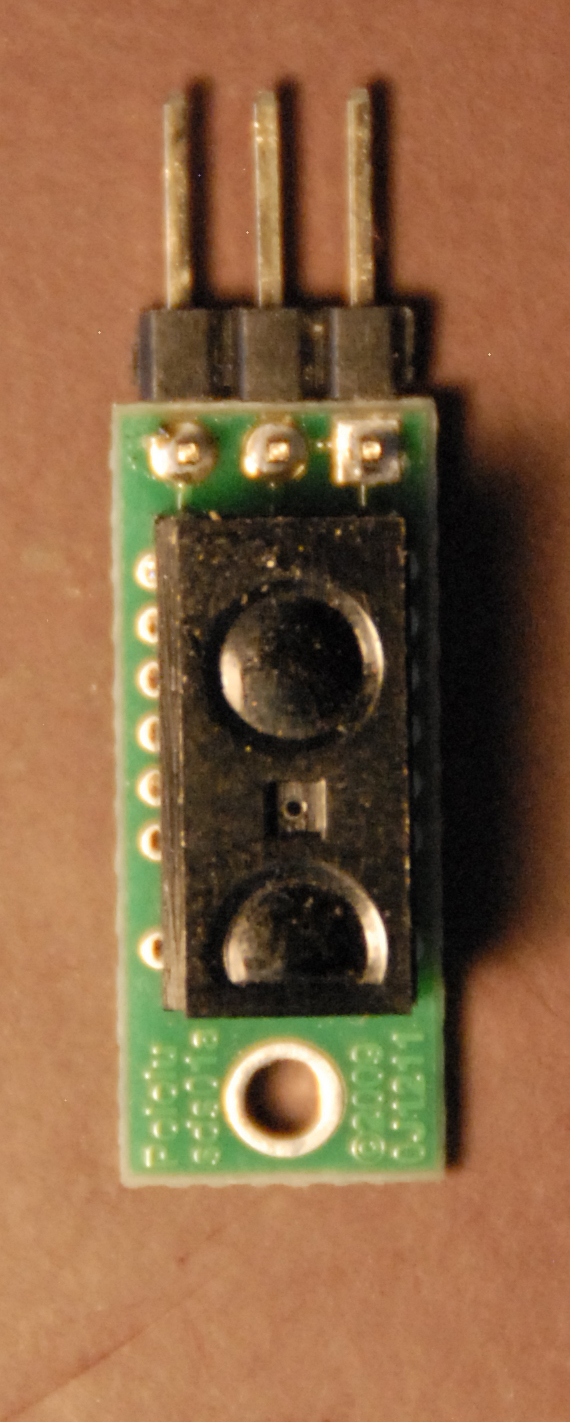
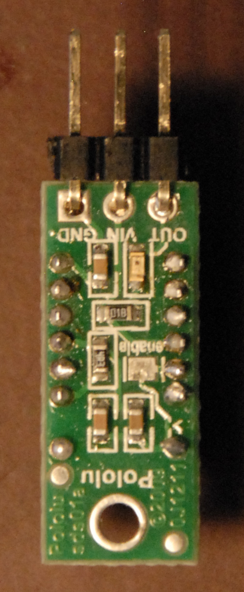
Can you post some clear pictures of the front and back of the most recently soldered sensor and board?
-Jon
Thanks for your reply, here are the requested images.
Your soldering seems fine, so I suspect that the sensor is damaged. You might try using it inside an unlit indoor environment. The lights in your house might emit infrared light in a manner that triggers this sensor. However, this sensor is generally robust enough not to be affected by ambient lighting. (Even when aiming two sensors directly at each other, we could not get the IR signal emitted from one sensor to interfere with the other sensor.)
By the way, did you get both your Sharp distance sensors and carrier boards directly from Pololu?
-Jon