I’ve a pair of GP2Y0D810 on Pololu carriers (bought via a UK Supplier), I’m using them for a simple minisumo and had expected them to be “short sighted”. They’re mounted back from the front edge of the minisumo as I’ve expected to loose detection 20mm from the sensor and gain detection around 100mm out.
What I’m seeing from the LED indicator is that I get an intermittent detection about 500mm out, this becomes solid about 400mm but it’s lost around 80mm out.
Has anyone else had this experience?
They’re powered from a regulated 5V supply, there’s no difference in the range with the output connected or disconnected to the target micro controller. At this time I’m not running the motors (there’s a degree of noise isolation on the board anyway).
I don’t remember hearing about anything like that. Are you sure about the detection distances (they’re 10x larger than I expect), and is it really correlated to detecting something at that distance as opposed to blocking something in the environment? Can you put a 10uF or so cap on the supply, close to the sensor, and see what happens?
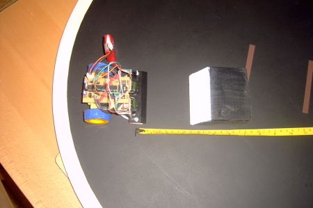
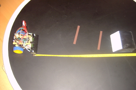
That distance is really what’s puzzled me! I’d a tape measure run out over the surface of my dohyo, just off to the side of the minisumo. The pictures are not great but they give you a good impression of scale and clear area - tape away from the area does change the results. (LED indication haven’t shown up)
If I go for my black fronted block I don’t pick up the object at all.
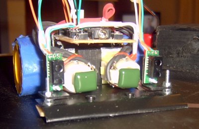
The general arrangement is show below. The sensor front is parallel to the vertical screw, this was to offer a little protection from the opponents scoop.
I’m not certain I follow the question.
I’ll give this ago tomorrow… it’s getting late here, too late to start firing up hot tools
Can you also try this test with different (detectable) objects? It would be interesting to see if the angle of the scoop is affecting the results. The sensor’s datasheet has some usage advice on page 6.
I tried the flat underside, which is a dull light green (treated wood finish). This was giving results consistent with the angled front. I’m off to work shortly, I’ll try the cap near the sensor when I return this evening.
In reality, on a minisumo I’m not going to be able to control the opponent. I didn’t expect an exact switching but did expect it to be around 100mm out and off again around 20mm. I’m trying to understand what might push the range so far!
When I’ve tried the IS471F style as a reflective sensor in the same set-up it gives range consistent with the tests I’ve seen reported around the web. Similarly Sharp Range Sensors and Maxbotic U-sonic have been responding as expected.
More testing and head scratching later… If it wasn’t for the increased dead zone up close I’d not be too worried - it’s boarder line on detecting too far out to be useful.
My question was just whether you’re really getting reliable detection of something at 50cm as opposed to generally noisy results that might have seemed correlated to the 50cm distant object. I hope it’s just a power supply issue that will get corrected with some capacitors at the sensors.
Right, this isn’t the sensor… hooking up to a separate battery supply it’s running as per spec.
I’ve not quite got to dropping a scope on the supply or adding the caps yet but at least I’ve ruled out the sensor itself as primary concern. I’ll update later when I’ve got a bit further.
Funny what you find after a good nights sleep
Mounting been done with an M2 screw, there’s two nylon washers between the board and the bracket to ensure that there’s no short circuit (I can manage the mechanical bits!).
I just had the same thing happen to me. I bought one of these a 2 months ago and I didn’t have a problem with it. I bought another one 2 weeks ago, I hooked it up today and it acted just as SLURP described.
Connected by itself to a battery it works fine.
Start adding a few wires to the circuit and it starts to detect infinity.
As Jan suggested, I did add a 10uf cap at the PCB and all is fine.
Having added the cap and run some additional jumpers across the back of my PCB (to be sure I’d a good supply) I’ve not managed to fix the response.
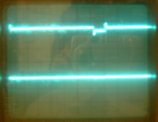
I finally managed to pull my scope out (I don’t have much work space). This is the first try at photos and my scope, I think I really need to turn intensity for the camera’s benefit!
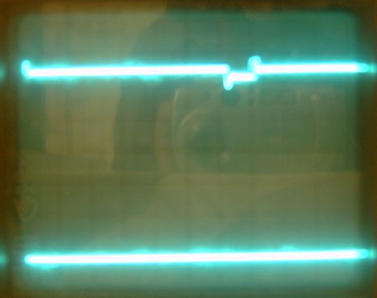
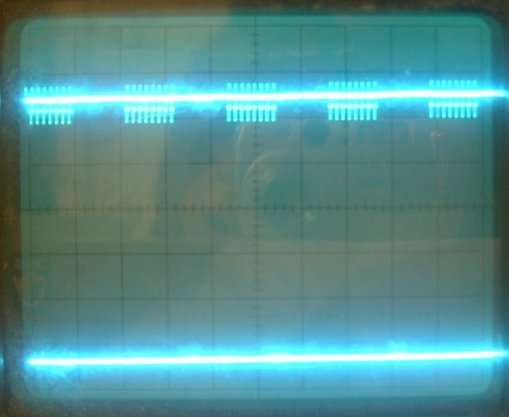
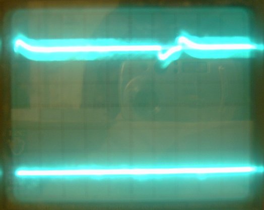
The first few pictures are taken with a 3v unregulated supply, initially with a 1usec time scale, top trace is the supply with a 0.1V blip. The last has a 1msec time scale where we can see this as a series of regular blips.
Looking at my 5v 1A Regulated supply the story is very different, there’s no brown out indicated by the micro-controller and there’s less than 20mV of noise without the sensor attached. The PCB has been in use for more than 12 months, I’ve not noted similar disruption to other sensors.
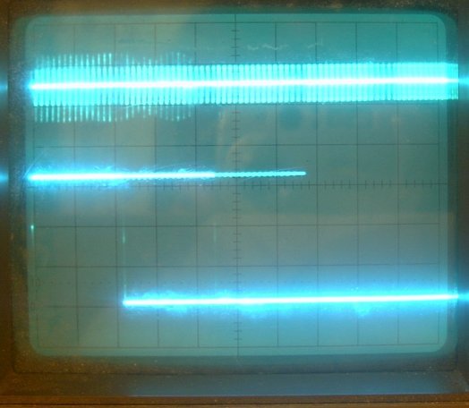
This first picture has no object in front of the object, the noise is broadly 0.1V the output is mostly showing detection - off appears to be 2msec - 6msec
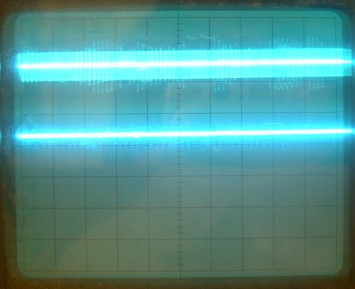
This next picture shows opposite of what I’d expect in the detection zone - high output & LED off, the signal is stable.
Similarly, when detection appears (up close but 4-5cm out) the signal is stable. With the 1usec time scale you can see the shape of the noise.
I’m really scratching my head, I’ve got a month to resolve the problem (next competition) but can fall back to my old sensors if I need to.
With these kind of problems, the details of how and where you’re measuring things can be significant. Are you measuring this right at the sensor, with your ground connection also there?
In general, the idea with the extra cap is to put it right at the sensor, not on your main PCB that is still separated by whatever wire you have going to the sensor.
I’ve added the cap looking end on the sensor PCB I’ve the wires coming in on the underside and the cap tagged onto the sensor side. All wire have been trimmed to a minimum 2-3 inches max.
Measurements have been made hooking on to these connections to the sensor, or when the sensors removed at my controllers connection point out to the sensor.
I don’t think I’ve a problem with the cap, but I’ll strip them off and re-check values of replacements tomorrow.