Hi,
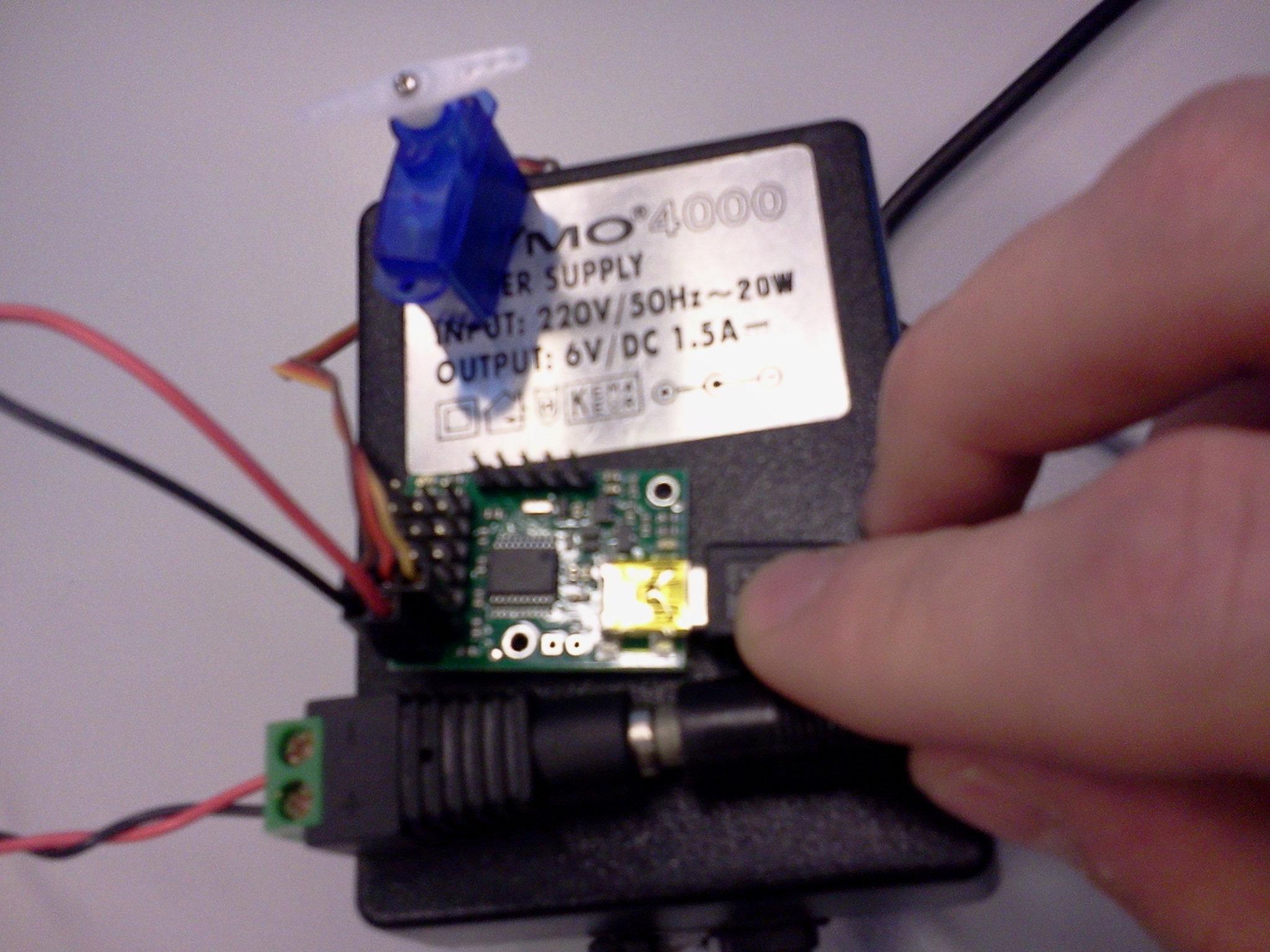
I don’t get started with my simple setup where I connected a wall adapter, to power a small servo, to the micro maestro. See picture attached. I think the voltage of the adapter should be ok, no? (6V). I try moving the position of the servo with the program that comes with the controller, as shown in the ‘getting started’ video on the page of the controller. The servo doesn’t respond at all. I first tried with the red and black wires exchanged, compared to the picture. I then noticed that the inside of my adapter plug is negative and the outside is positive. That’s why I changed the black and red wires that comes from the adapter plug. Nevertheless, the result was the same: no response at all. The Maestro does give a green and orange led light. I tried each time, with the maestro connect to the PC with the USB connection.
I hope I didn’t destroy my electronics. Any help is very much appreciated.
Hello.
That 6V power adapter should work for powering your servo. If your power adapter is center-negative, the connections shown in your picture look correct; however, if the voltage applied to the servo was backwards at some point, the servo is likely damaged. I expect the Maestro to be unharmed since the servo power rails are separate from the logic side of the Maestro board. Does everything seem to be working properly in the Maestro Control Center, except you are not getting a response from the servo? Do you have a different servo you can try? Could you describe what the two indicator LEDs that you mentioned are doing?
-Brandon
yes, as far as I understand, the software is working ok. I have 2 of this tiny servo, so 1 other. But I don’t want to risk to destroy it, because than I’m out of servo’s. The green led, I believe from the USB, is flashing very rapidly. When the servo position control is moved in the software, it’s on and less/not flashing during this operation. The orange led at the side of the channels is giving 2 flashes in a periodic way.
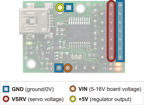
The LED behavior you are describing sounds normal. If you want more certainty before connecting the other servo, you might try measuring the voltage on the Maestro’s servo power rails with a multimeter to make sure the power is connected in the right orientation. The row of pins closest to the edge of the board should be ground, while the middle row of pins should be positive, as shown in this picture:
Also, it is good practice to only change connections while there is no power applied to your system.
-Brandon
I read 5.8 V DC between center channel pins (to multimeter ‘V’) and ground pins (to multimeter ‘COM’) using this adapter.
I checked another adapter with variable voltage output. I set it on 6V. It is a 600 mA adapter with high efficiency, overload and short circuit protection, eco friendly design. With this one I only read tiny voltage changes and minus or plus is not clear as it changes often. This has to do with these ‘protection’ mechanisms?
Should I try the first adapter with my last and only servo, now?
I do not know about the second adapter you mentioned, but the first one (in your picture) looks like it should be fine. As long as you connect your servo and battery wires in the correct orientation, there should be no danger to your servo.
-Brandon
So far, I believe the servo is still alive. When connecting the power adapter, the servo starts buzzing and becomes quite hot within seconds, while the wheels or top arm of the servo are not moving. Since it doesn’t sound very healthy I pulled out the power adapter. It doesn’t respond to the servo control slider in the software at ‘buzz’-time.
I made the connection from the adapter plug to the micro master with my own wires, that are somewhat thicker than for example those from the servo to the micro maestro. That should not be the problem right?
I do not suspect your wires are causing a problem. You might try double checking that you are moving the slider for the correct servo channel. In your picture, the servo is connected to channel 0. Have you changed the parameters in the “Channel Settings” tab? The mode should be set to “Servo”, and you should make sure it is not commanding the servo beyond its endpoints. You can check this by making sure the Min and Max values in the “Channel Settings” tab are set to appropriate values for your servo. Most standard servos work with pulse widths between 1000us and 2000us.
-Brandon
I’m getting closer: the second adapter didn’t give voltage on the channels because, despite various types of adapter plugs, it didn’t get in contact with either the inner pin or outer shell. I’ve put some alu foil at the outer shell and now it gives a nice voltage of almost 6V. Now, my first servo is definitely broken in the inside circuit: it doesn’t do anything.
The second servo didn’t move the arm but did get power. so I opened the topside of the servo. It appears that one wheel shaft was broken off. But what I see is that when I use the servo (opened-up) with the software (so without mechanical connection between primary servo output wheel and the following plastic wheels) it is under speed control instead of under position control when using the slider. Is this normal for this servo (Pololu Sub-Micro Servo 3.7g (Generic))? Is this because there’s normally feedback via the final wheel shaft, that is necessary to have position control? Because when it was closed, it only buzzed without moving: I believe the motor was running against a blocked set of wheels, generating heat.
That servo normally has position control, but it sounds like the feedback is probably connected to the broken part of the shaft. Without that feedback, the servo will not be able to do position control.
-Brandon
With my newly ordered servo it works now. Thanks for the help!
Still 2 questions:
Is there an easy way to get 360° rotation and position control? I guess not.
Can you damage the gearwheels and shafts by screwing in the screw of the servo-arm? (rotational force)
I am glad it is working now; thank you for letting us know. There are servos that allow for a full rotation or more while still offering position control. The one we carry is currently out of stock, and we do not know when it might be available again, but you might try doing an Internet search for “sail winch servo”. As for your question about tightening the screw on the servo horn, it might be possible to damage the servo in that way if you are not careful and force the servo beyond its end point (especially with the sub-micro servos).
-Brandon