I have recently worked with these boards, and while they are quite functional and off a lot of computer power - the board design itself presents a number of problems.
On the 328PB the 5 horizontal pins across the bottom (end opposite FTDI pins) do nothing but cause problems, On any breadboard - solder or solderless - these pins will be shorted together. Yes you can run wires to them - but that defeats the ability to socket the board. It would have been so much more useful to simply run all the pins down each side! I’ve just struggled using this chip on a strip board, and those pins are a nightmare. If you need to use all the extra pins this chip offers - BEWARE of the end pins,
So I’m going to replace the 328PB with a 32U4 - it’s pinout is close enough to the Nano I was using with which I ran out of pins. But - Once again some “creative board design” has added problems to using this chip/board. I can’t imagine why there are screw-mounting holes on each end… WTF is THAT about?? I’ve built numerous project with such boards and have yet to “wish for a screw mount hole”! Of course now the (useless) screw-mount holes offset the spacing of the pins on each side of the board… For what gain? NONE I can see. So to use this in the socket where my Nano was I will have to add 2 socket pins to each end.
Not bad products overall - but you need to be cautious when laying out a project which will use them.
Breadboards are for circuit verification only and are extremely unreliable in the real world.
If you want to put a module in a robot, or any environment where vibration and movement could be a problem, you will avoid breadboards completely, use wires and solder all connections, or (less reliably) use gold plated pins and socketed cables, and securely mount your MPU and other modules using the very convenient mounting holes.
You totally missed my point! I would NEVER use a SOLDERLESS breadboard for a finished circuit. They are bad enough to debug and plan with.
I use some form of solderable PROTO board (as this is a one-off project and doesn’t warrant a full custom PCB ) and now strip board. I have all “BOB’s” with pins soldered to each location on the board and the I use female headers as sockets for them (as nothing else fits). And with the processor in a socket SOLDERED to a board, along with other components like stepper drivers or displays or whatever - All mounted on the protoboard board which has screw-holes in each of 4 corners and is on stand-off’s - this seems like a fairly sturdy structure - AND the processor or other complex boards (drivers, etc) and be removed and replace if there is a failure.
Somehow I can’t think of a way one would mount an MCU board to a circuit board and have a place (or need) for mounting screws. Seems like a very bizarre concept.
I did not suggest mounting modules or MPUs to a circuit board. In my devices, they are mounted to other surfaces, using screws and nuts through the very convenient mounting holes.
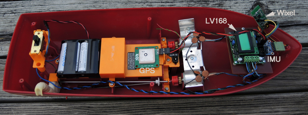
An example is shown below, of a tiny boat that autonomously navigates through a series of GPS waypoints on open water. Note how the Pololu Orangutan LV168 is mounted using screws and standoffs, as is the BNO055 IMU. (The Wixel hanging in space is for temporary debugging, since replaced by the Sparkfun OpenLog for a permanent course log).
The issues you raise appear to result more from the limitations of your imagination, rather than significant problems with the board design.
I think you might be the first person complaining about mounting holes existing on some of our products; the few complaints I remember were always about there not being mounting holes. Designing products like ours involves balancing many opposing requirements our customers have. Usually, people want the boards smaller (so they fit in more places) and with mounting holes, and just those two considerations are already at odds since adding mounting holes usually makes the boards bigger. Compatibility with other existing products, whether in terms of physical size and shape or operating voltage or some other aspect, is another common requirement, and making boards “same enough” while adding features or improvements is a challenge since different applications require different things to stay the same.
In the case of the A-Star 328PB Micro, we wanted to keep the common size and as much of the pinout as we could of the Arduino Pro Mini type products while providing access to some of the extra pins that the ATmega328PB offers. Those extra pins that you are complaining about are still on a 0.1" grid, so you can socket them on a protoboard or stripboard using female headers. If the location of the pins and the pattern on your stripboard would cause a short, you can just make a few cuts in those copper traces, and you can still end up with a socketed A-Star 328PB on a protoboard that uses all the pins. (And if you don’t need those pins, you of course don’t need to solder them in to begin with.)
On the A-Star 32U4 boards, you can see that we have the Micro version that is smaller and without mounting holes, and the Mini versions that are bigger and have the mounting holes that are bothering you so. Your annoyance seems largely based on your expectation relative to the Arduino Nano. Presumably there’s some reason you’re not just using the Nano, so you can see you have another case of wanting a board that’s different enough from the Nano while also being the same enough.
Jim, thanks for sharing that boat picture! It’s October, so I think it must be 14 years now since we met at Robothon in Seattle. Or maybe it was the 2005 contest, which would make it 13 years. I remember you having some kind of criticisms about the Orangutans, which I hope I put to good use in our products. It’s great to see you still using them!
Ok - it is just that I must be using a different construction technique than most. (and that does NOT result in a “Limited Imagination”!)
Here is a link to some pix of how I build stuff: BoardWork
There are some pix of what happens when you cut the traces between the end pins on a 328PB on a strip board - soldering nightmare! Also some overall views to show - YACS (yet another construction style!)
I don’t use Shields and after the solder-less prototype is working, I build the design on solder proto-boards with point-to-point wiring. All the “BOB” type parts (like A-Star processors, and stepper driver boards) are soldered with male header pins, and the on the final board, female headers are used as sockets. Since most of these BOB parts come on a board requiring header pins in future projects I’ll have to have 2 of each part: one for the solderless BB and one with machine-pin (Swiss) headers and sockets.
I’ll give you the mounting holes as there ARE other ways (I guess) to mount these boards. Not a real biggie… But the holes across the bottom? Just can’t reconcile that one!
I just attempted to use a strip-board and cutting the traces between those end pins was a mess - but did get it done and have a header socket. Personally the length added by two extra pins on the sides would not be a game-changer! Take a look at the pix in the slideshow
Also - on a solderless BB they would be shorted together. And if used in a design where the board was in a socket, and the end pins direct-wired - it would kill the point of the socket!
I had to replace my Nano (in header sockets) with the A-Star 32U4 board and was able to add in the 2 extra pins on each end (with the help of my friendly Dremel tool), and so on this board I will be able to replace the processor should it ever fail.
I’ve just learned of the 32U4 boards - and LOVE the 4 hardware interrupts - just wish 2 of them weren’t on the same pins as SERIAL1. All good stuff - hope to be using more in the future.