Hello,
I bought the 10cm FSLP and connected it to my arduino. I have adjusted my fine-tune poti to the desired 4.6k and used the schematics provided on your website and the arduino sketch.
Beside that the resolution of the internal ardu-ADC gives me only 1024 digits, I found that my FSLP doesn’t give values to the whole 10cm, it only gives digits for the half of the FSLP.
My question, could you support me with some (handdrawn) schematics how to use Adafruit’s ADC ADS1015 ->link to product with the FSLP ? Then I’m able to use 4096 digits for (hopefully) the whole slider.
It sounds like the problem you are describing is that your readings go from 0 to 1023, but it only corresponds to half of the length of the sensor. You should be able to read the full 10cm of the sensor using an Arduino; the difference between the Arduino ADC and the one you linked to is the resolution, so I do not think reading it with the ADS1015 would fix the problem (e.g. it would just give you more resolution between the point that reads 0V and the point that reads 5V).
By default, the 10cm FSLP will only function in the first 2.5cm of the sensor. To have the sensor function over one of the predesignated lengths, you will need to cut the sensor as indicated in the “Customizing the strip length” section of the FSLP’s product page. More information about doing this can be found in the FSLP customization guide. Have you cut the strip as indicated on its product page? If so, can you post some pictures of your setup that show all of your connections?
Hi Brandon,
thanks for the quick reply. Yeah, one has to cut the little ears. Now as I know this I see this on the product-page too.
Now it works, but I still want a higher resolution so I’d like to refresh the question of a (handdrawn) schematic to use the Adafruit ADC ( I use it for other analog things , very good product).
I have not used the ADC1015 breakout board from Adafruit, but it looks like it uses I2C communicate to the Arduino, so you would connect that as shown in the I2C Connections or I2C “Classic” sections of the Adafruit 4-Channel ADC Breakouts guide you linked to in your first post.
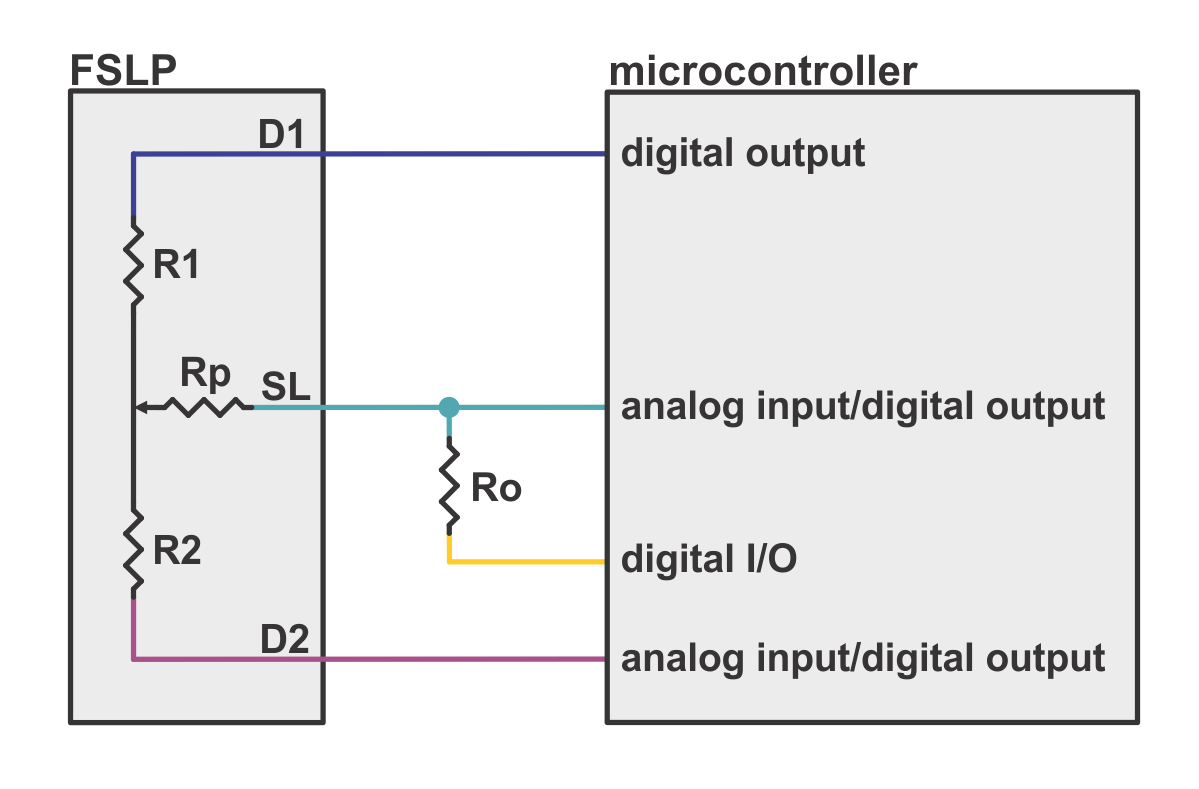
How to connect the sensor to the ADC breakout board might depend on how you are using the sensor. For example, if you want to measure position, you will need to have the ability to drive the different pins high or low and take an analog reading from them at various times while taking the measurements (see the “Measuring position” section of the FSLP’s product page for more information about this). Since the ADC breakout cannot drive pins (it cannot use its input pins as outputs), you cannot simply disconnect the wire from your Arduino and connect it to the ADC breakout. Instead, you will probably want to connect D2 and SL (shown in the pictures below) to the ADC breakout board pins (e.g. A0 and A1) with a jumper wire, and leave them connected to your Arduino as well. Then when the instructions for taking the reading call for you to measure the input, you would use I2C communication to get the measurement of those pins through the ADC breakout board.
If you make a wiring diagram and post it here, I would be glad to take a look and see if I see anything obviously wrong with it. Also, if you have not tried it yet with just the Arduino, you might consider seeing if it works fine for your application; I suspect the Arduino ADC resolution (which should theoretically give you a resolution of about 0.1mm for the position measurement) is high enough for most applications with the FSLP.