I recently obtained a small laboratory spectrophotometer that had been discarded, and was surprised that the diffraction grating was directly driven by a 5-phase, ten wire Vexta motor. The optics were in perfect shape and useful for other projects, but there is little information on the web about how to drive a five phase stepper, and there are no working examples that I could find with Arduino.
Of course, you can buy a five phase driver from Oriental Motor Company (Vexta manufacturer) for about USD $200, but another option is to use an Arduino Pro Mini, and three much less expensive brushed DC motor drivers from Pololu.
The motor specs: Vexta PX33M-A-C6 0.21A, 33 Ohms per phase, 0.36 degrees/step. Ten wires.
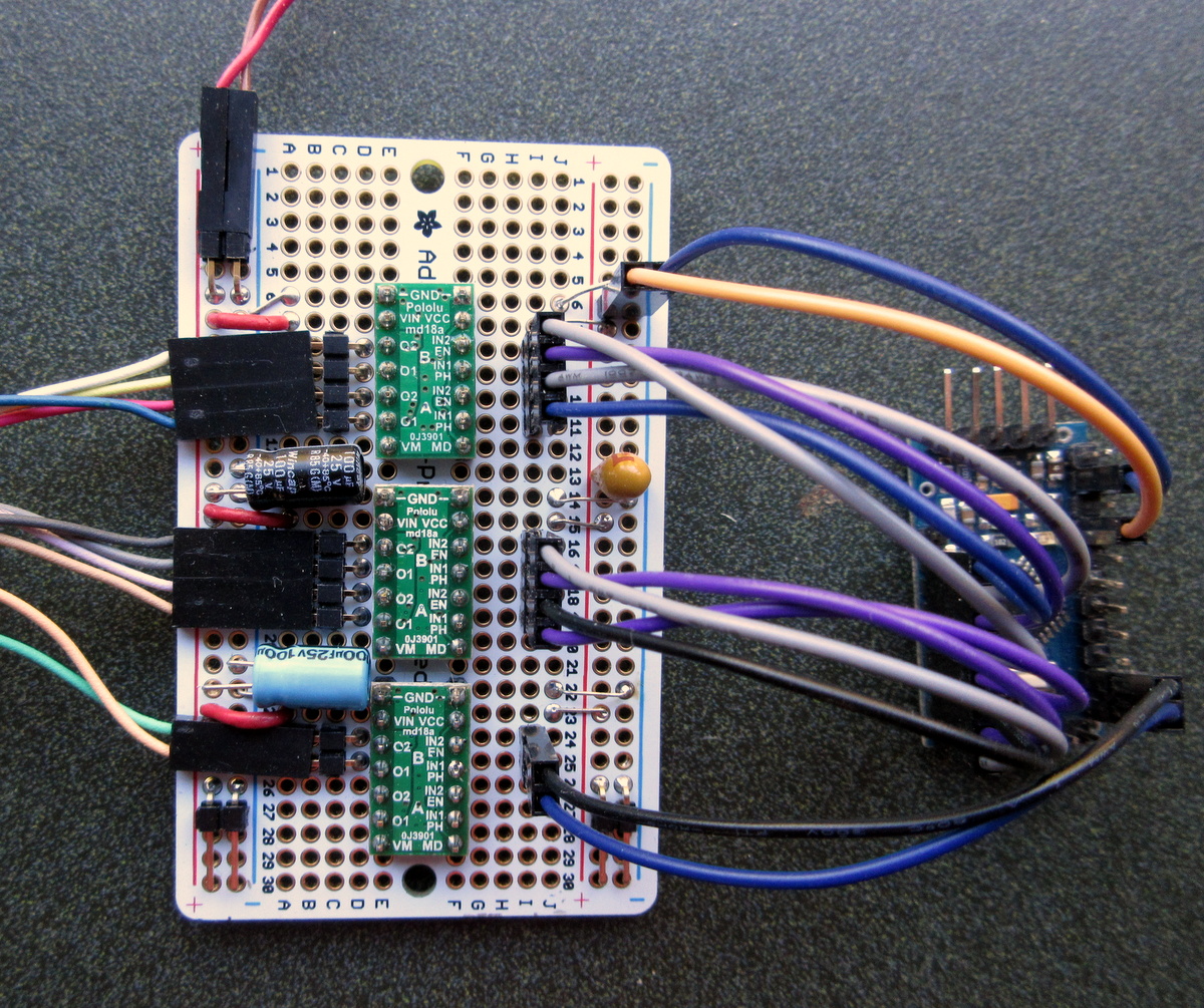
The low current rating and moderate winding resistance means that direct drive from 5 to 6V is possible, avoiding the need for a chopper stepper driver. I decided to use three Pololu DRV8835 dual full bridge modules (only five H-bridges are used, leaving one free for other uses), and with dead simple code it is capable of executing 500 steps/sec from dead stop, without skipping a single step. Half step drive is available, for 2000 steps/revolution, capable of better than 500 steps/second.
See it move 1000 steps in real time.!
Vital information below, used as a guide in creating the working example.
- There is confusion on the web about motor coil and wiring color code with lead assignment. I started with this diagram, which supposedly reveals the coil and winding start/finish order:
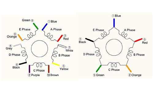
But the motor connector had white/yellow and grey/black reversed from the sequence above. The driver works with swapped connections (as long as both pairs of the two connections are reversed) but obeying the connector wire order resulted in the smoothest and presumably correct operation. That is, swap white/yellow and black/gray.
My decision to swap those leads is supported by the alternative assignment of wire colors and winding identifications in the PDF file below. Evidently Oriental Motor is not consistent with wire color codes. 5_Phase_Penta_Connection.pdf (44.9 KB)
-
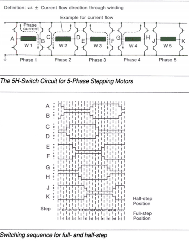
Coil excitation sequence, half and full step.
-
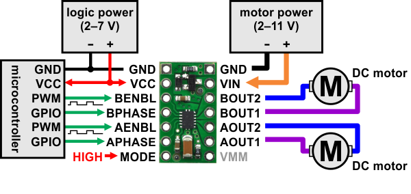
Wiring diagram for two of the phases (micro used was the Pro Mini). The complete pin assignments and subsequent connections are detailed in the code below. Image from Pololu product page: Pololu - DRV8835 Dual Motor Driver Carrier
- TOTALLY UNOPTIMIZED but fully functional code. Note that the drive tables are cyclic permutations of each other, so only one is required (ten bytes of storage in the optimized version).
// five phase drive for Vexta PX33M-A-C6 0.21A, 33R per phase, 0.36 degrees/step
// S. J. Remington 10/2020
// Totally unoptimized code!
// 3x Pololu DRV8835 dual motor driver
// **IN/IN mode selected**
// Truth Table
// IN1 IN2 OUT1 OUT2
// 0 0 open open
// 1 0 H L
// 0 1 L H
// Vexta PK PX, wire colors in order around the motor
//A - blue > red
//B - white > yellow (reversed on motor connector, polarity switched)
//C - brown > purple
//D - black > gray (reversed on motor connector, polarity switched)
//E - orange > green
// smoother action with white/yellow and black/gray both reversed
// drive sequences from 10_wire_sequence.png
// NOTE that these tables are cyclic permutations of each other, so only one is actually required.
// This is the dead simple, brute force version. Optimized version to be posted later
/*
// half step
// 1 2 3 4 5 6 7 8 9 10 11 12 13 14 15 16 17 18 19 20
int AB[20] = { 1, 0,-1,-1,-1,-1,-1,-1,-1,-1,-1, 0, 1, 1, 1, 1, 1, 1, 1, 1};
int CD[20] = {-1,-1,-1, 0, 1, 1, 1, 1, 1, 1, 1, 1, 1, 0,-1,-1,-1,-1,-1,-1};
int EF[20] = { 1, 1, 1, 1, 1, 0,-1,-1,-1,-1,-1,-1,-1,-1,-1, 0, 1, 1, 1, 1};
int GH[20] = {-1,-1,-1,-1,-1,-1,-1, 0, 1, 1, 1, 1, 1, 1, 1, 1, 1, 0,-1,-1};
int JK[20] = { 1, 1, 1, 1, 1, 1, 1, 1, 1, 0,-1,-1,-1,-1,-1,-1,-1,-1,-1, 0};
*/
// full step (1000 steps/revolution)
int AB[10] = { 0, -1, -1, -1, -1, 0, 1, 1, 1, 1};
int CD[10] = { -1, 0, 1, 1, 1, 1, 0, -1, -1, -1};
int EF[10] = { 1, 1, 0, -1, -1, -1, -1, 0, 1, 1};
int GH[10] = { -1, -1, -1, 0, 1, 1, 1, 1, 0, -1};
int JK[10] = { 1, 1, 1, 1, 0, -1, -1, -1, -1, 0};
//
int index = 0;
int index_max = 10;
void setup() {
//pin driver -> motor assignments
pinMode(2, OUTPUT); //A blue, I1, O1 MD1A
pinMode(3, OUTPUT); //A red, I2, O2, MD1A
pinMode(4, OUTPUT); //B yellow, I1, O1, MD1B
pinMode(5, OUTPUT); //B white, I2, O2, MD1B
pinMode(6, OUTPUT); //C brown, I1, O1, MD2A
pinMode(7, OUTPUT); //C purple, I2, O2, MD2A
pinMode(8, OUTPUT); //D gray, I1, O1, MD2B
pinMode(9, OUTPUT); //D black, I2, O2, MD2B
pinMode(11, OUTPUT); //E orange, I1, O1, MD3A
pinMode(12, OUTPUT); //E green, I2, O2, MD3A
}
void loop() { //execute 1000 steps at full speed, from dead stop
for (int i = 0; i < 1000; i++) {
if (AB[index] > 0) {
digitalWrite(2, 1);
digitalWrite(3, 0);
}
if (AB[index] == 0) {
digitalWrite(2, 0);
digitalWrite(3, 0);
}
if (AB[index] < 0) {
digitalWrite(2, 0);
digitalWrite(3, 1);
}
if (CD[index] > 0) {
digitalWrite(4, 1);
digitalWrite(5, 0);
}
if (CD[index] == 0) {
digitalWrite(4, 0);
digitalWrite(5, 0);
}
if (CD[index] < 0) {
digitalWrite(4, 0);
digitalWrite(5, 1);
}
if (EF[index] > 0) {
digitalWrite(6, 1);
digitalWrite(7, 0);
}
if (EF[index] == 0) {
digitalWrite(6, 0);
digitalWrite(7, 0);
}
if (EF[index] < 0) {
digitalWrite(6, 0);
digitalWrite(7, 1);
}
if (GH[index] > 0) {
digitalWrite(8, 1);
digitalWrite(9, 0);
}
if (GH[index] == 0) {
digitalWrite(8, 0);
digitalWrite(9, 0);
}
if (GH[index] < 0) {
digitalWrite(8, 0);
digitalWrite(9, 1);
}
if (JK[index] > 0) {
digitalWrite(11, 1);
digitalWrite(12, 0);
}
if (JK[index] == 0) {
digitalWrite(11, 0);
digitalWrite(12, 0);
}
if (JK[index] < 0) {
digitalWrite(11, 0);
digitalWrite(12, 1);
}
delay(2); //500 steps/second OK
// decrement index to drive in the reverse direction
index++;
if (index == index_max) index = 0;
if (index < 0) index = index_max;
}
delay(500);
}
I’ll post optimized code when I figure out the best way to proceed.
For the pentagon wiring option, five half bridge drivers are used. Improved step sequences for the pentagon connection are shown in the PDF file below from Oriental Motor.
vexta_pentagon_phase_sequence.pdf (59.2 KB)