Hi Everyone!
Recently, i studied most of the “fast line follower robots”. 75% of these use Pololu’s micro metal gear motors, QTR-8A/8RC, any motor Driver and Li-Po+Boost Converter.
I made a line follower of mine based on the same hardware. The result is quite satisfying
the video attached shows the initial build. the robot is slow but accurate. The details of the bot in short are–
MCU : Atmega328P @ 16Mhz
Supply : 7.4v
Motor Driver Supply : 9v (via boost converter)
PWM Value : 60
Size of bot : the size of a credit card
Control Algorithm : PD Controller
the most impressive line follower is saw was Hirai San’s Cartis 04.
Now i want to modify my bot completely; speed, hardware and software. Regarding this i have few questions as well as some issues i encountered while attempting to speed up the bot.
****** ISSUES *******
when i step up the motor driver supply voltage or the PWM value, the bot overshoots,particularly at the corners.
small chassis and fast bot, don’t go hand in hand.
i had to define two drive routines: one for corner turning and one for normal line following. This led to improper line following sometimes.
4.Motor takes time to change its direction/speed. This delay became significant when speed of the bot was high.
****** QUESTIONS / DOUBTS *******
1.How do i tackle the overshooting? (Especially at the corners)
2. when i make the chassis longer (increasing the distance between sensor and the motors), balancing the bot became an issue. the wheels were not able to maintain contact with the ground. ( i used LEDs instead of castor wheels ). So, how do i ensure stability while using a longer chassis?
3.Differential is a must for crisp corner turns. Technically, two drive routines should work , but in my case line following wasn’t quite smooth on some parts of track, when i had two drive routines. Where did i go wrong?
4.How to tackle the time delay of motors?
5.Will, changing to an MCU clocked at freq. > 16Mhz, help? In fact, does the MCU Clock speed affect the performance in my case?
6. choosing a motor with gear ratio between 10:1 - 30:1 will require me to make the chassis longer which resulted in instability for me. Any advice?
7.how important is wheel selection? I’m using Pololu slick wheels. Should i switch over to thin, bigger diameter wheels?
8. Is/are there any other control algorithm(s) for line followers? should i switch to some different algorithm? (the core of my code is similar to Pololu 3pi’s Line Following sample code)
9.Can someone shed some light on Cartis 04? any information on its hardware, software, build, algorithm will help
Most (possibly all) of the line following robots I have seen in our local competitions use a PD control system. I found it easiest to increase the speed of my line followers slowly (e.g. increase the maximum speed, test it, re-tune the P and D values if necessary, and repeat). If increasing your speed leads to more overshoot, you probably need to lower the P coefficient or raise the D coefficient.
There are some important considerations when designing the robot. A lot of faster line following robots tend to extend their sensor out in front of the robot, like the one in your second video. This helps account for the delay time in the motors that you mentioned and gives your robot some insight to what is ahead, so it is easier to react to. However, it also puts more mass in front of the robot, which could cause problems, especially when turning at higher speeds. In my experience, it works out well if you can keep most of the weight situated close to the center point between your wheels. I gave some insight into this in the blog post for my line following robot (The Chariot).
Wheel selection can be very important since it determines your top speed and torque. A wheel with a larger diameter will give you more distance per revolution of your motor, while a smaller diameter will give you more torque. You can find details about how to calculate this in this Force and Torque blog post. The tires are also important since they effect your traction. At higher speeds, you might start to see some sliding. I originally used a pair of sticky tires on The Chariot, but I did not notice a significant difference between those and the tires that come with our wheels at high speeds. One thing to note though is that both tires perform much better when clean. At our local competitions, we usually have a little cleaning station for the people who are going next to get ready.
The course used in your second video is interesting. It has some long straightaways and some fairly tight U-turns. The course even crosses over itself at one point. A more difficult course like that typically uses some kind of indicator for the robot to sense more about what the course is doing (you can see these in the video as little dashes of tape along the sides of the course at the beginning and end of each turn). Sometimes, such as with right angle turns, it is best to do some extra processing to detect the turn and run a different portion of code to handle the obstacle. For example, our MazeSolver example program from our Zumo for Arduino library uses a basic line following algorithm to follow the line until it detects a turn (which are all specified as right angle turns); once a turn is detected, it goes to a different function to execute the turn.
You are suggesting me to decrease the P gain and increase the D gain, wont that make my bot less responsive? since the P part counters the error, decreasing P will decrease the corrective measure magnitude.
Also, theoretically, increasing the D and decreasing the P will make my bot more sensitive to fluctuations
my bot overshoots mainly at the junctions. for. Eg on a straight line with a 90 degree turn at the end, the bot flawlessly follows the line but it goes ahead of the turn. As a result the wheels fail to align with the turn properly.
2.i"ll consider using 2 different routines: one for line following and other for sharp turns
3.So,following the Zumo’s sample maze solving code, you mean to say the flow of my code should be–
if ( no turn detected )
followSegment();
else if ( turn detected )
{ determine_Turn(); turn(); }
should i stick to qtr-8A’s analog values to determine the turn or should i use it as a digital sensor?
one more issue. i ran the bot yesterday at my home ( i printed the arena used for competition ). the bot performed flawlessly! it took the correct turns every time.
However during the competition, the bot didn’t perform as expected. At the same junction, sometimes it took the correct turn sometimes it didn’t. What could be the reason? Should i shield qtr-8A?
Thanks!
Most of your questions can share the same answer: every robot is different and there are many ways to tackle different obstacles, so you will have to determine what will work for your robot. For example, I cannot say for sure how to change your P and D coefficients to increase the performance of your robot, but it will likely take quite a bit of trial and error to get it right. Decreasing the P coefficient will make it less responsive to the error proportionally, but increasing the D coefficient will increase its response to changes in the error.
As far as your sensor choice, we generally recommend the digital versions of our QTR reflectance sensors over the analog ones, but both will work. You can find more details of the benefits of using the digital ones from my post in this thread. With either version of the sensor, ambient lighting can cause variations in performance (e.g. fluorescent lights or large windows letting in sunlight can be tricky for the sensors to handle). It is usually a good idea to test and tune your robot in as close to the same environment as you will be competing in, but shielding the sensors could help alleviate as well. Also, note that the sensors measure the IR light reflected off the surface, so if your printed course did not use the same material, that would likely cause some differences.
Depending on your hardware, a different microcontroller might be able to outperform others; however, in your application, it is unlikely that the microcontroller frequency is the limiting factor, so you probably won’t see a noticeable difference between a 16 MHz and 20 MHz microcontroller.
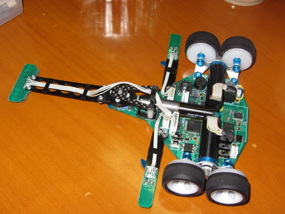
I did some research on cartis03; its mechanical built, mechanics involved and the hardware used.
I found some things quite unusual. I wonder if you could help me with that
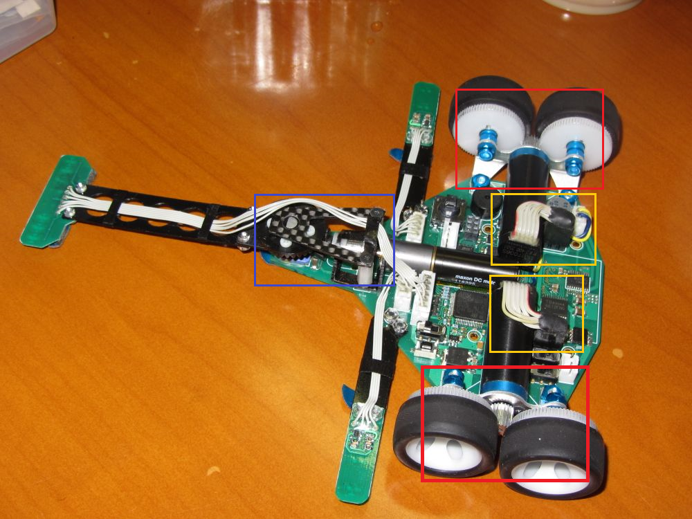
DRIVE SYSTEM [ Red Box]
The motor shaft isn’t directly coupled to the wheel. It is coupled to TWO (not one but two!) wheels via a gear.
So,what is the thing with the drive system? when the motor shaft rotates, I wonder how the two wheels(coupled to one motor) move in same direction?
Can somebody help me identify which motors and wheels are those? where can i buy them?
2.THE MOTORS [ Yellow Box]
The motors have 6 wires, I guess it has an encoder attached to it.
Why use an encoder?
[The Blue Box]
This one is rather interesting. There’s a motor in the center of the chassis (maxon DC motor).
This motor’s shaft is coupled to a black gear (its inside the blue box). The sensor is attached to a black extension strip which is connected to this black gear.
I watched some of cartis03’s videos in slow-mo. I found that the motor indirectly moves the sensor sideways in order to “look” into turns and corners as you said earlier (it gives enough time for the motors to change their state)
Any tips/techniques on how to do it?
That is a really neat robot; it looks much more complex than a typical line follower.
I suspect the reason for having two wheels on each side is to get an increased output from the motors as well as more traction. Both wheels should turn the same way since they are coupled with the motor (i.e. the drive or pinion gear) in the middle of them. Here is a nice visual of how that would work (note that the middle gear is the drive gear).
Again, I can’t say for sure what the encoders are being used for, but I suspect if the course has indicators like I mentioned in my previous post, the robot can use the encoders to quickly drive in a straight line (or a specified curve). They might also be used for speed feedback so it can adjust to a slower speed around corners.
I don’t have any suggestions for moving the sensor to look around the corner; it would probably require a separate PID algorithm for doing closed-loop position control with the motor coupled to the sensor.
Thank you so much Brandon for sharing the visual! I found the build description of the robots that participated in RoboTrace. I found that-
1.These guys use high RPM Swiss made core less motors and use gear reduction to get sufficient torque.
2. 50% of the participants used Stm32. Out of 100+ participants, hardly 5 used Atmega328p/Atmega16/Atmega32.
3.Almost every robot is equipped with encoders and gyro.
4.Most of the robots have “moving sensors” as I highlighted earlier.
I have attached the PDF for your reference if you want .The last 5-10 pages highlight the components used by the participants. (the PDF is in Japanese, so you may have to use google translate for that).
I tried reaching some of these participants, but they haven’t replied so far. If you know anyone who is/are into advanced line followers, is it possible I could talk to him/them?
Just came by this topic, since I’m planning to build the next one too.
Btw great research so far
Watching the video of Curtis04 it seems that the first run is to explore the track and memorize straight sections. Then on the following runs, the robot knows when it can do full speed and when it has to slow down.
So wheel encoders allow it to track these distances and I’d guess that gyros are used to determine hardness of the curves more precisely.
( On the second/third runs you can see, that the robot slows down just before the curves. )
Just curious: have you done any more research on those followers?
Sorry for the late reply sir.
Yes i have looked into the mechanical build and the hardware used.
But the main part is the software used,what algorithm runs under the hood and how is it way more efficient than the ones we make.
There’s very little information about the bots Japanese guys make.