Well, here it is. This is my updated code which allows calibration and stores the results in the eeprom program space. Any comments and suggestions welcome.
Tim.
/*
* RC 3pi
*
* This 3pi robot program reads two standard radio-control (RC) channels and mixes
* them into motor control. Channel zero (connected to the PD0 input)
* handles forward and reverse, and channel one (connected to the
* PC5 input) handles turning.
*
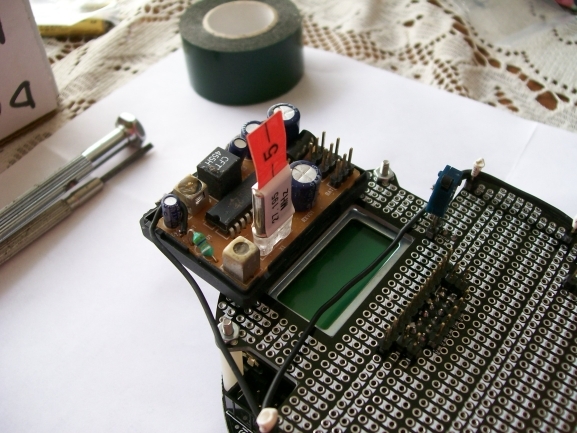
I am using an 8 channel input, connect to channels 1 and 3 on the rc receiver
and to the pins on the 3pi in the positions shown below.
1 2 3 4 5 6 7
------------------------------------------
|CH3 NEG|CH3 SIG| | | |CH1 SIG| |
------------------------------------------
| | |CH1 POS| | | | |
------------------------------------------
CH3 SIG = PD0
CH1 SIG = PC5
*/
#include <avr/io.h>
#include <avr/interrupt.h>
#include <pololu/3pi.h>
#include <avr/eeprom.h>
#define bool short
#define true 1
#define false 0
// define the full battery charge and empty battery charge so that
// it will display % charged to the user on button c press.
#define FULL_BAT_MV 5800
#define EMPTY_BAT_MV 4900
/////
// Standard startup function. I always display the battery
// voltage and percentage charged at the start of the programs
// as letting it go flat and re-programming it seems a very bad idea.
/////
void waitForStartCommand() ;
// I want to store the min/mid/max values for channels 1 and 2 in the eeprom
// memory so that I do not have to run the calibration each time. Define the
// initial values here as well.
// **** Remember to program these onto the robot too from the .eeprom file. ***.
uint16_t EEMEM ch0_min = 300;
uint16_t EEMEM ch0_mid = 450;
uint16_t EEMEM ch0_max = 600;
uint16_t EEMEM ch1_min = 300;
uint16_t EEMEM ch1_mid = 450;
uint16_t EEMEM ch1_max = 600;
// This is to catch errors.
const int maxLowPulseTime = 3000;
struct ChannelStruct
{
// volatile as they are going to change within the isr.
volatile unsigned int prevTime;
volatile unsigned int lowDur;
volatile unsigned int highDur;
volatile unsigned char newPulse;
unsigned int pulse;
unsigned char error;
// Each channel now has its own set of min/max/mid stick positions.
int min ;
int mid ;
int max ;
} ;
// capture the two channels.
struct ChannelStruct ch[2];
/*
* Pin Change interrupts
* PCI0 triggers on PCINT7..0
* PCI1 triggers on PCINT14..8
* PCI2 triggers on PCINT23..16
* PCMSK2, PCMSK1, PCMSK0 registers control which pins contribute.
*
* The following table is useful:
*
* AVR pin PCINT # PCI #
* --------- ----------------- -----
* PB0 - PB5 PCINT0 - PCINT5 PCI0
* PC0 - PC5 PCINT8 - PCINT13 PCI1
* PD0 - PD7 PCINT16 - PCINT23 PCI2
*
*/
// This interrupt service routine is for the channel connected to PD0
ISR(PCINT2_vect)
{
// Save a snapshot of PIND at the current time
unsigned char pind = PIND;
unsigned int time = TCNT1;
if (pind & (1 << PORTD0))
{
// PD0 has changed to high so record the low pulse's duration
ch[0].lowDur = time - ch[0].prevTime;
}
else
{
// PD0 has changed to low so record the high pulse's duration
ch[0].highDur = time - ch[0].prevTime;
ch[0].newPulse = 1; // The high pulse just finished so we can process it now
}
ch[0].prevTime = time;
}
// This interrupt service routine is for the channel connected to PC5
ISR(PCINT1_vect)
{
// Save a snapshot of PINC at the current time
unsigned char pinc = PINC;
unsigned int time = TCNT1;
if (pinc & (1 << PORTC5))
{
// PC5 has changed to high so record the low pulse's duration
ch[1].lowDur = time - ch[1].prevTime;
}
else
{
// PC5 has changed to low so record the high pulse's duration
ch[1].highDur = time - ch[1].prevTime;
ch[1].newPulse = 1; // The high pulse just finished so we can process it now
}
ch[1].prevTime = time;
}
/**
* updateChannels ensures the recevied signals are valid, and if they are valid
* it stores the most recent high pulse for each channel.
*/
void updateChannels(bool calibrating)
{
unsigned char i;
for (i = 0; i < 2; i++)
{
cli(); // Disable interrupts
if (TCNT1 - ch[i].prevTime > 35000)
{
// The pulse is too long (longer than 112 ms); register an error
// before it causes possible problems.
ch[i].error = 5; // wait for 5 good pulses before trusting the signal
}
sei(); // Enable interrupts
if (ch[i].newPulse)
{
cli(); // Disable interrupts while reading highDur and lowDur
ch[i].newPulse = 0;
unsigned int highDuration = ch[i].highDur;
unsigned int lowDuration = ch[i].lowDur;
sei(); // Enable interrupts
ch[i].pulse = 0;
// Humm. I seem to get a bit of error at maximum speed/turn. This seems
// to be because it is 1 or 2 over the min and max positions. Add a little
// margin for error here before calling the pulse an error.
int maxPulse = ch[i].max + 50 ;
int minPulse = ch[i].min - 50 ;
// Note that we only test for out of range values on the min and max
// when we are not calibrating, otherwise we don't know what are good
// values.
if (lowDuration < maxLowPulseTime ||
( !calibrating && (highDuration < minPulse ||
highDuration > maxPulse) ) )
{
// The low pulse was too short or the high pulse was too long or too short
ch[i].error = 5; // Wait for 5 good pulses before trusting the signal
}
else
{
// Wait for error number of good pulses
if (ch[i].error)
ch[i].error--;
else
{
// Save the duration of the high pulse for use in the channel mixing
// calculation below
ch[i].pulse = highDuration;
}
}
}
}
}
void printCalibrationResults( long ch0, long ch1 )
{
clear() ;
print( "Ch0" ) ;
lcd_goto_xy(0,1) ;
print_long( ch0 );
delay_ms ( 500 ) ;
clear() ;
print( "Ch1" ) ;
lcd_goto_xy( 0,1 ) ;
print_long( ch1 ) ;
delay_ms(500) ;
}
void getCalibration( const char* text, int *ch0, int *ch1 )
{
clear() ;
print( text ) ;
lcd_goto_xy( 0,1 );
print( "Then B" ) ;
// wait for a button b press and a good signal. the user should have moved
// the position of the sticks during this time.
while(!button_is_pressed(BUTTON_B) ||
ch[0].error || ch[1].error )
{
updateChannels(true) ;
}
// capture this position.
*ch0 = ch[0].pulse ;
*ch1 = ch[1].pulse ;
}
void calibrate()
{
// Get the min/max and middle sticks and store on the channels.
getCalibration( "Middle", &ch[0].mid, &ch[1].mid) ;
printCalibrationResults( ch[0].mid, ch[1].mid ) ;
getCalibration( "Max/Rght", &ch[0].max, &ch[1].max) ;
printCalibrationResults( ch[0].max, ch[1].max ) ;
getCalibration( "Min/Left", &ch[0].min, &ch[1].min) ;
printCalibrationResults( ch[0].min, ch[1].min ) ;
}
void loadSettingsFromEEPROM()
{
// for both channels load the settings from eebrom. Note that
// we use the eeprom functions for this and pass the address
// of the int within the eeprom program space as an argument to
// this function.
ch[0].min = eeprom_read_word(&ch0_min);
ch[0].mid = eeprom_read_word(&ch0_mid);
ch[0].max = eeprom_read_word(&ch0_max);
ch[1].min = eeprom_read_word(&ch1_min);
ch[1].mid = eeprom_read_word(&ch1_mid);
ch[1].max = eeprom_read_word(&ch1_max);
// debug. print the loaded settings.
printCalibrationResults( ch[0].min, ch[1].min ) ;
printCalibrationResults( ch[0].mid, ch[1].mid ) ;
printCalibrationResults( ch[0].max, ch[1].max ) ;
// TODO: Catch errors. Check that the .eeprom file has been programmed
// onto the robot.
}
void writeSettingsToEEPROM()
{
// Save the current settings so that they persist when the robot is
// turned off.
eeprom_write_word(&ch0_min, ch[0].min) ;
eeprom_write_word(&ch0_mid, ch[0].mid) ;
eeprom_write_word(&ch0_max, ch[0].max) ;
eeprom_write_word(&ch1_min, ch[1].min) ;
eeprom_write_word(&ch1_mid, ch[1].mid) ;
eeprom_write_word(&ch1_max, ch[1].max) ;
}
unsigned int errortime = 0 ;
void drive()
{
updateChannels(false);
if (ch[0].error || ch[1].error)
{
// This bit of code is a bit experimental really. I am attempting to
// give a delay when the signal is lost of 500ms to avoid small gitches.
// the user won't notice this loss of control.
// TODO: Test this code - not sure it works correctly.
unsigned int time = TCNT1 ;
if ( errortime == 0 )
{
errortime = time + 500 ;
return ;
}
else if ( time < errortime )
{
// don't shut down yet
return ;
}
// Ok switch off.
errortime = 0 ;
set_motors(0, 0);
return ;
}
// good result so reset error time
errortime = 0 ;
// This is basically the mix code from the example, but i scale each channel between
// -255 and 255 first and then mix them. When forwards = 0,0, it will allow -255,255 of rotation.
// when forwards is 255,255 it will give 0,255 of rotation.
// TODO: Make this neater.
long forwards = -(ch[0].mid - (int)ch[0].pulse) ;
long rotation = ((int)ch[1].pulse) - ch[1].mid ;
// scale both forwards and rotation so that they are -255 to 255.
forwards = forwards * 255 / ( ch[0].mid - ch[0].min ) ;
rotation = rotation * 255 / ( ch[1].mid - ch[1].min ) ;
// now we simply do the mix. If we are not going forwards we can rotate
// faster (i.e. +255,-255) than it we are going flat out as this would result
// in 255,0. This is fine and what we want.
long m1 = forwards + rotation ;
long m2 = forwards - rotation ;
// Clamp the values.
if ( m1 > 255 )
m1 = 255 ;
if ( m1 < -255 )
m1 = -255 ;
if ( m2 > 255 )
m2 = 255 ;
if ( m2 < -255 )
m2 = -255 ;
// Print the motors speeds.
if (get_ms() % 1000)
{
lcd_goto_xy(0, 0);
print("m1 ");
print_long(m1);
print(" ");
lcd_goto_xy(0, 1);
print("m2 ");
print_long(m2);
print(" ");
}
set_motors(m1, m2);
}
int main()
{
// wait until b is pressed before starting.
waitForStartCommand() ;
ch[0].error = 5; // Wait for 5 good pulses before trusting the signal
ch[1].error = 5;
DDRD &= ~(1 << PORTD0); // Set pin PD0 as an input
PORTD |= 1 << PORTD0; // Enable pull-up on pin PD0 so that it isn't floating
DDRC &= ~(1 << PORTC5); // Set pin PC5 as an input
PORTC |= 1 << PORTC5; // Enable pull-up on pin PC5 so that it isn't floating
delay_ms(1); // Give the pull-up voltage time to rise
PCMSK1 = (1 << PORTC5); // Set pin-change interrupt mask for pin PC5
PCMSK2 = (1 << PORTD0); // Set pin-change interrupt mask for pin PD0
PCIFR = 0xFF; // Clear all pin-change interrupt flags
PCICR = 0x06; // Enable pin-change interrupt for masked pins of PORTD
// and PORTC; disable pin-change interrupts for PORTB
sei(); // Interrupts are off by default so enable them
TCCR1B = 0x03; // Timer 1 ticks at 20MHz/64 = 312.5kHz (1 tick per 3.2us)
// load the calibration settings from eeprom.
loadSettingsFromEEPROM() ;
clear() ;
print( "B>Start" );
lcd_goto_xy(0,1) ;
print( "C>Setup" ) ;
// Ok, wait for another button B press to start. Button C
// launches the calibration.
while(1)
{
if ( button_is_pressed(BUTTON_B) )
break ;
if ( button_is_pressed(BUTTON_C) )
{
calibrate() ;
// Save the settings so that they persist when turned off.
writeSettingsToEEPROM() ;
clear() ;
print( "B>Start" );
lcd_goto_xy(0,1) ;
print( "C>Setup" ) ;
}
}
// Now just do the drive code forever.
while (1)
{
drive() ;
}
// This part of the code is never reached. A robot should
// never reach the end of its program, or unpredictable behavior
// will result as random code starts getting executed.
}
/////
// Startup functions.
/////
void displayBattVoltage()
{
int bat = read_battery_millivolts();
clear();
print_long(bat);
print("mV");
}
void displayBattPercent()
{
int bat = read_battery_millivolts() - EMPTY_BAT_MV;
float p = ((float)bat / (FULL_BAT_MV-EMPTY_BAT_MV))*100.0 ;
clear();
print_long((int)p);
print("%");
}
// waits for a button b press before running the main application.
void waitForStartCommand()
{
typedef void (*DISPLAY)(void);
DISPLAY cb = displayBattVoltage ;
// I always start a program with button B and display
// the voltage or percentage.
while(!button_is_pressed(BUTTON_B))
{
cb() ;
lcd_goto_xy(0,1);
print( "Press B" );
if ( button_is_pressed(BUTTON_C) )
{
cb = displayBattPercent;
}
else if ( button_is_pressed(BUTTON_A) )
{
cb = displayBattVoltage ;
}
delay_ms(100);
}
clear() ;
// delay a bit after the press before doing stuff.
delay_ms(1000);
}


 , and will set it up with the RC and camera built in. I’ve also ordered another 3 Pi, addictive little buggars aren’t they?