My project uses two voltage regulators: S9V11F3S5 for the 3.3V processor and S9V11F5S6CMA for the 5V electronics.
My processor already has brownout detection, so I don’t need to use an enable pin to protect from low battery voltage. Instead, I just want to use the enable pin to shut down the 5V electronics for power savings. I’m finding it rather clunky to use it for this purpose because the enable pin is configured to, in essence, monitor the input voltage.
My specific problem is that there are really three states. When the processor is powered, the digital output pin controlling the enable pin is either logical high or low. That works fine. However, if the processor is switched off then the pin floats and the enable pin is driven by its own internal battery level detection. I actually don’t want this. I want the 5V regulator to be off when the processor is off.
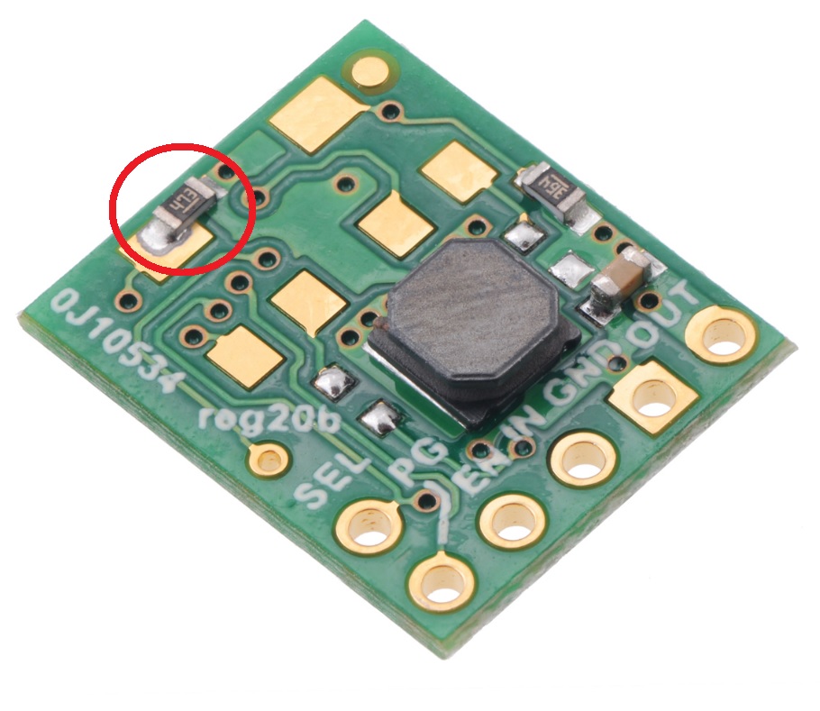
I’m guessing there is a pullup resistor on the regulator that causes the pin to go high enough to trigger the enable. If so, can I just remove it and explicitly control the output with a logic level on the enable pin? There would also have to be a pulldown resistor that would cover the situation where the pin is floating. I suspect there is already a pulldown resistor, but I don’t know. Just looking for the best solution. Thanks.