I’m using an Orangutan SVP 1284, with Pololu 100 to 1 gear motors with the encoder board attached. I’m trying to run the following code, but only 0 and 1 print on the LCD. I don’t see any messages about errors.
#include <pololu/orangutan.h>

int main()
{
    svp_set_mode(SVP_MODE_ENCODERS);
    set_motors(200, 200);

    unsigned long x = 0;
    while (1)
    {
        lcd_goto_xy(0,1);
        print_long(svp_get_counts_ab());
        print(" ");

        lcd_goto_xy(4,1);
        print_long(svp_get_counts_cd());
        print(" ");

        if(svp_check_error_ab())
        {
            lcd_goto_xy(0,1);
            print("Error 1");
        }
        if(svp_check_error_cd())
        {
            lcd_goto_xy(0,1);
            print("Error 2");
        }

        delay_ms(50);

    }
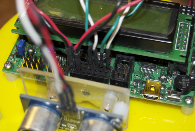
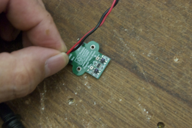
I’m using a 6 x AA battery pack with new batteries, and the wheels are spinning like champs, but I’m not getting the increasing measurements I was expecting. I’ve searched around but haven’t found another post about this, so I’m probably just not hooking something up right. Here’s a shot of how I’m connecting the pins from the encoders
The quality isn’t very good, sorry. Each encoder has a green and white wire connected to it, and I’m plugging one pair into A and B, and the other set into C and D.
I’d appreciate any ideas about what I’m doing wrong.
Thanks
Joe (the code feature doesn’t seem to be working, sorry)
First of all, thanks for simplifying your system/code and providing a picture. That has saved us both a lot of time!
The right-most white wire in your picture is plugged directly in to ground, and you didn’t connect anything to D. Try moving all four wires one space over.
Okay. Well, how are you powering the encoders? And are you using the right wheel?
It would be nice if you could measure the voltages coming out of the encoders. If you don’t have a multimeter or oscilloscope, you can use the SVP itself by loading the precompiled SVP demo program on to it. It’s available in the Pololu USB AVR Library in a folder that’s something like examples/atmega…p/hex_files/svp-demo-program.hex. The analog part of demo will display the readings from A, B, C, and D and all the analog inputs on the AVR as a bar graph. You should verify that A, B, C, and D are being read properly by the auxiliary processor and reported to your AVR (use a wire to change their voltages on A, B, C, and D and see if your actions affect what shows up on the bar graph).
Once you are able to read the voltages of the encoder outputs, turn off the motor and just turn the wheel slowly by hand. If the encoders are working, both encoder outputs should switch from 0 to 5 V several times each turn, and they should switch out of phase with eachother (one should switch before the other one).
Sorry it took so long to respond about this, but life got in the way for a while there.
I have wires coming from the power connectors on the encoder board, plugging into the headers with the data wires. I’ve just checked them again, and they are plugged into the right holes.
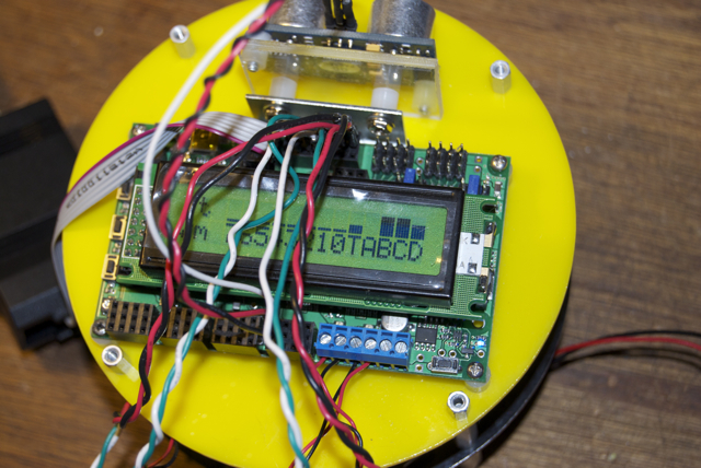
I’ll upload a picture of the bar graph. It doesn’t change if I turn the wheels or not.
In my previous post, I said you should verify that A, B, C, and D are being read properly by the auxiliary processor and reported to your AVR and I suggested manipulating the voltage on those pins with a wire (while your encoders are not connected). You could also just disconnect the encoders and then reconnect them in reverse and make sure that the bar graph readings switch accordingly. Have you verified that A, B, C, and D are being read properly by the auxiliary processor and reported to your AVR, and if so, how? Until you do this, we can’t trust the readings on the bar graph.
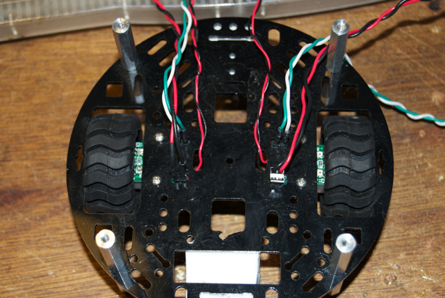
Also, in my previous post I asked you if you are using the right wheel. What wheel are you using? Does your setup look like this picture?
It looks like you have the “Disable BBCode” option checked when you make your posts, yet you’re still including BBCode in your posts (e.g. [ quote ]). Your posts would be more readable if you enabled BBCode. Note that I fixed all of your posts above by allowing BBCode.
In my last two posts I suggested manipulating the voltage on the A, B, C, and D pins with a wire while your encoders are not connected. If the bar graph readings on the LCD change accordingly, (e.g. go high when the line is connected to VCC and go low when the line is connected to GND) then this will allow us to trust the readings on the bar graph. You should test each line (A, B, C, and D) by making it go both high (VCC) and low (GND). Be careful not to short anything while you are doing this.
I tried plugging the positive line from a 5V power supply into each one, and then did the same with the negative line from the same power supply. The bar graph for each line (A,B,C & D) went to max and flickered there. It acted the same way for both positive and negative leads.
Then I plugged in the power lines for one of the encoders, and inserted the signal leads for that encoder into C and D. The bar graph for D went up about half way and stayed solid (no flickering), and the bar graph for C went up about half that, again no flickering. Turning the wheels by hand didn’t change anything.
Thank you for doing a test to confirm that your bar graph reading is related to the voltage on A, B, C, and D lines. You probably got flickering because the separate 5V power supply that you plugged in to those lines did not share a command ground (GND) with the SVP. You should have just used the GND and VCC pins that are available all in many places on the SVP, for example the GND and VCC lines you are using to power your encoders. That’s OK though, from your description I’m pretty sure that the bar graph is working so we can move on.
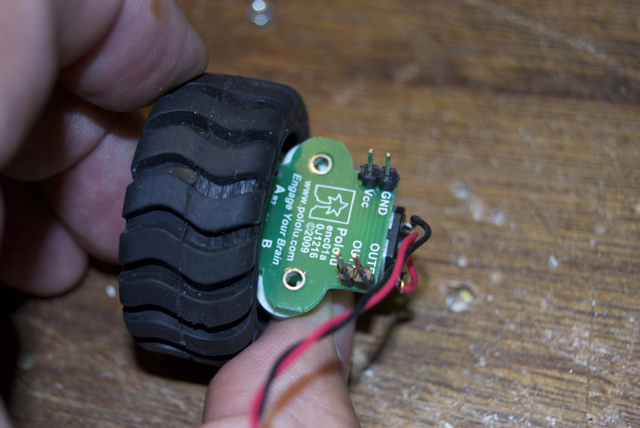
You haven’t yet posted any pictures of how your encoders and how they wired/installed in your robot. You should post a picture or pictures of that and maybe we’ll catch something that’s wrong. The picture(s) should show the wires that you soldered in to the encoder and also the electronic components on the encoder. You’ll probably have to remove the wheel to get a good picture of those components.
While the wheel is off, please find out whether the encoder’s infrared LEDs are emitting any light. You can’t see it with your eyes, so you will have to use some kind of camera that doesn’t have an IR filter. Most cell phone cameras and probably any non-expensive digital camera should work. It helps if you go to a dark room. While looking at the encoder through the camera, you should see two little dots coming from the LEDs. If you unplug the encoder power wires, you should see those dots disappear. If you see this, then we’ll know that your encoders are powered. It should be easy to tell what’s going on, but if you’re not sure what you are seeing, you can post those pictures here and we’ll take a look at them.
I hope that you didn’t turn any of the potentiometers on the encoder board, because that could make the encoders stop working. If you have turned them, definitely let us know.
I don’t see lights, but I have a color vision problem with blue/read stuff. Here’s a picture though, it was about a half second exposure with the desk light turned off so it’s kind of blurry. I think I can see a couple red spots there, but it might be my imagination.
I think I found the (a?) problem. When I was putting things back together I realized that I had the signal wires on the wrong posts for one of the wheels. I got things upside down in my head when I put it together maybe.
Anyway, now when I run the demo program and turn the wheels the levels on B and C change. I don’t see anything for A and D though, should there be a change there as well?
So I’m trying to run the original code again (pretty much). The reading for the right wheel is either 0 or -1, and the reading for the left wheel is either 0 or 1.
I don’t want to be a pain, but how should the wires from the encoder be plugged into A,B,C & D? Does it matter as long as the same signal from each wheel goes into A/B and the other signal goes to C/D?
Well, never mind. The SVP won’t hold a program any more anyway. When I load a program it runs ok until I remove the programmer cable and turn it on again. Then I get nothing on the LCD but blocks in each position, and it doesn’t do anything. If I plug the cable back in and re-flash it, it works fine again until I remove the programming cable.
I guess I’m dumber than a bag of hammers and shouldn’t be playing with electricity.
So are you giving up or would you like help on this latest problem?
Probably our batteries just need to be charged, and right now they are outputting a voltage that is too low for the AVR to run (brown-out) but high enough for the LCD to startup and display its default contents (top line full of black boxes and the bottom line empty).
Sorry, I’m having a bad day, I’ve been trying to get ADC working on an ATtiny13A with no luck, seems I can only do PWM or ADC but not both. I’m a little frustrated and should have walked away from the keyboard.
I reloaded the sample program, which ran fine without the programmer cable, so I don’t know what’s happening. I thought I was a little farther along the power curve than I apparently am with this hardware stuff. I’m sure I just messed something up and I’ll figure it out eventually. Thanks for your help, but I’m sure you have other things to do.