
I want to develop a project using this encoder. Does anyone can help me how to measure the distance using this encoder and briefly explain how this encoder read the signal because it using 2 input A and B, why?
Hello.
This product is just a standard quadrature encoder, so you should be able to find a lot of resources online that explain how they work. For example:
en.wikipedia.org/wiki/Rotary_enc … ry_encoder
zone.ni.com/devzone/cda/tut/p/id/4763
You can measure distance and speed using just one of the two encoder channels (A or B), but you need to use both channels if you want to know direction. Using both channels also gives you twice the resolution.
- Ben
Thanks for reply
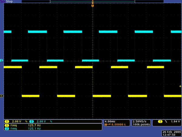
And one more thing in this website https://www.pololu.com/catalog/product/1217 there is some information that mention about the spinning wheel 630RPM, it is fix speed for this encoder? and if slower or faster any effect?
The motor used for the oscilloscope capture just happened to be spinning at 630 RPM. There is nothing special about that speed.
- Ben
Based on this picture how we want to know how much pulse for one rotation? Because we want to apply it in this formula
![]()
where N = number of pulses generated by the encoder per shaft revolution
x = encoding type
Where PPI = pulses per inch (a parameter specific to each encoder
The wheel has twelve teeth (so each channel generates 12 pulses per revolution) and the wheel diameter is approximately 42 mm (1.65 in).
- Ben
thanks Ben for your information, hope you’ll stick to this thread in case I have more question to ask
Can I apply this formula
![]()
http://zone.ni.com/devzone/cda/tut/p/id/7109
to measure the distance (for one complete rotation) without using counter for my encoder?
Or maybe I need a little help, that you can show me how to use this formula (for one complete rotation), thanks in advance.
That formula is just a very general way of telling you how to measure distance traveled for an encoder. I’ve given you the specifics for this encoder in my previous post. There are twelve pulses per rotation, and the diameter is 1.65 in. From the diameter, you can compute the circumference of the wheel:
C = piD = 3.141.65 in = 5.2 in
If you have twelve pulses per rotation, that means that you have approximately one rising pulse edge per channel every 5.2in/12 = 0.43 in. If you also track the falling edge, you can get down to half this resolution, and if you use both rising and falling edges of both encoder channels, you can get down to a quarter of this resolution (approximately 0.1 in).
The simplest way to use your formula is to note that for every twelve pulses you detect on a single channel, your wheel has gone 5.2 inches, so distance traveled for x pulses is x*5.2/12 inches (or 0.43x inches).
- Ben
Hello its me again… 
I want to build a robot using DFRduino Duemlianove 328, 2A Motor Shield For Arduino and Pololu 42x19mm Wheel and Encoder Set, how to make the wiring connection between of these 3 main part so the robot can be functioned properly?
Is it any extra circuit board that I need to use?
Thanks in advance
Hello.
I wrote the equations for dead reckoning of a differential drive robot using rotary encoders here on Wikipedia: http://en.wikipedia.org/wiki/Dead_reckoning
- Ryan
Hello Ryan could you help me build my robot with all the component that I already mention?
Hi.
I’m not going to make the circuit for you, but if you post your attempt at the circuit I can look at it.
- Ryan
OK this is all my component that I want to use it for building my robot. Can you show me:
-how to do wiring for each component?
-is there any extra circuit that I need to have?
-how many power supply do we need because for the
*DFRduino Duemlianove 32 need about 5V
*2A Motor Shield For Arduino (voltage depend on desire speed, for this case we want to use 7V)
*Pololu Encoder need about 5V
Pololu Wheel 42X19mm with the gear motor

DFRduino Duemlianove 328

2A Motor Shield For Arduino

Combination between DFRduino Duemlianove 328 and 2A Motor Shield For Arduino

7V Battery

I’m sorry, but we don’t have time to do your project for you, especially when that involves telling you how to use another company’s products. If you have very specific questions or run into trouble, please feel free to ask for help, but you have to be able to exercise a certain level of resourcefulness and figure some things out on your own using the information that is already out there. Our encoder product page explains the encoders in detail, and I’m sure there are plenty of web pages out there that talk about how to use the DFRduino and the motor shield.
- Ben
OK no problem about that, sorry for trying to burden you, one last thing that I want to know which is how to transfer the pulse that has been generated by encoder to the microcontroller?
BTW Ryan, thanks for the dead reckoning link. My first attempts at trying that particular trick ran afoul of poor traction on the wheels, making the robot think it was making progress when in truth a wheel was simply spinning. (Darned warped hand-made chassis.)
Is there any provision in the Pololu controllers to sense current draw to the motors and provide that back to software? I’d guess that a spinning wheel would draw far less current than one that is actually pushing, and that distinction could be used to repair the erroneous counter calculations.
Come to think of it, I suppose I could construct a current sensor of some sort and feed it back as an analog I/O source. Hmmm…
Hi, zolofy,
As the product page for the encoder states, “The two outputs of the encoder are digital outputs that can be connected directly to digital input pins on most microcontrollers (inputs that can generate interrupts on change are recommended).” You can simply use wires to connect OUTA and OUTB to the I/O pins on your microcontroller that you plan to use for counting encoder ticks. Programming the microcontroller to actually interpret the pulses is up to you.
- Kevin
OK thanks for your information, I’ll try it. I’ll post the feedback, hope you’ll stick to this thread.
Hi, Lertulo
You’re welcome. I think that you would be able to get some better performance out of current sensing, but it might be easier to just address your slipping problem. Maybe with something like these sticky tires?
The motor controllers we offer that can report the current being used are the jrks and TReXs. You can get the current with a serial command. A lot of our motor drivers – MC33926, VNH2, and our some of our high-power motor drivers – have current sensing built in. We also offer current sensors.
- Ryan