
Hello is it possible to use the drv8876 without logic power? I mean I intebr to power the dev8876 with 10v foe example and from thz schematic in the datasheet I must feed the logic power between. So very naive quesrion I have: can we use it without ligic power? The 2 first modes LOW and HIGH need logic power. In the third mode the PMODE is not connected does it mean we have no need of logic power and what does half bridge means? Thanks
Hi.
The sleep pin on the DRV8874 must be tied to a voltage between 1.8V and 5.5V (generally your logic level voltage). This could come from a logic power supply or from an I/O pin on a microcontroller. The term half-bridge refers to the two sides of a H-bridge like those used in many brushed DC motor drivers. This Wikipedia article on H-bridges might be helpful. More information on the DRV8874 half-bridge mode can be found in its datasheet.
If you are still unsure about how to connect your driver, you could post more about how you want to use it along with a diagram showing your proposed connections and I would be happy to take a look.
-Claire
Dear Claire thanks for your prompt and clear answer. Please find in the attached file my schematic. The aim is to power and drive a motor for train turnouts. Please assume that the PIN 5 of the attiny85 is no more the Reset pin but “delivers”
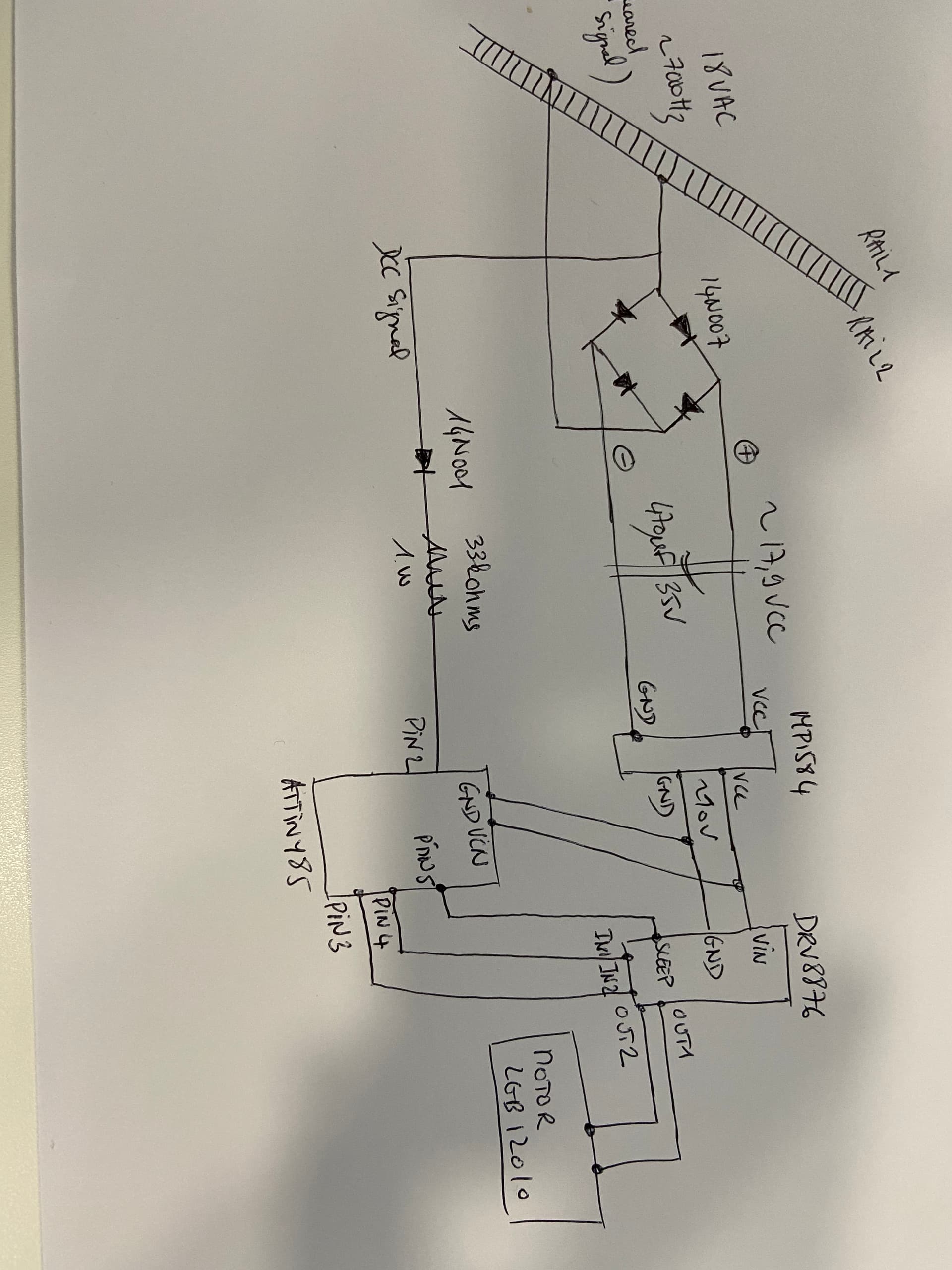
power around 2v.
I have already tested the schematic with a L298n and. It works. Before tryinh could you please have a look on the wiring I al thinking about? Thanks. Laurent.
If you want to operate the DRV8876 in IN/IN mode, you should connect PMODE to a high signal too. If you will not be using nSLEEP to actually put the driver to sleep (just holding it high all the time) you could connect PMODE to nSLEEP. Also, pin 4 on the ATtiny85 is either GND or DNC depending on which package you have, though maybe you are actually using PB3 and PB4 to control the IN pins of the driver.
-Claire
Okay. Sorry for my very naive questions on EN/PH mode is my code correct?
I have connected PMODE to GND of the Attiny.
#define SleepMode 5  // SLEEP connected to PIN5 of the attiny85
#define EN 3 // PIN3 connected to EN of 8876
#define PH 4 // PIN4 connected to PH of 8876


void setup() {
  Serial.begin(115200);
  pinMode(SleepMode, OUTPUT);
  pinMode(PH, OUTPUT);
  pinMode(EN,OUTPUT);

  digitalWrite(SleepMode, HIGH);// put SLEEP on high (between GND and SLEEP I get 3,8V).


}

void loop() {
  digitalWrite(PH,1);  // forward
   analogWrite(EN,255); // speed max
  delay(5000);

   digitalWrite(PH,0); // backward
    analogWrite(EN,255); // speed max
  delay(5000);
}
thanks
That code looks okay assuming that all your connections are correct. Note though that switching from full-speed forward to full-speed reverse can be stressful for a motor and cause voltage spikes that could damage a driver. You might consider stopping the motor briefly in between.
-Claire
With arduino it s working very well.
But with attiny85 I am struggling to wire correctly.
Between GND and SLEEP I got 4,7V from the PiN1 of the attiny85. Motor is powered with 9v (checked from the dev8876). But nothing happens. The attiny is resseting continuously.
My apologize. It s working well with attiny85 digispark. I was powering from usb cable. So Port 3 and 4 were disable. With an other source of power, Port 0 and 1 are fine for EN and PH respectievly. Port. 3 is fine for SLEEP (for mode EN/PH).
Super driver. Thanks.
1 Like