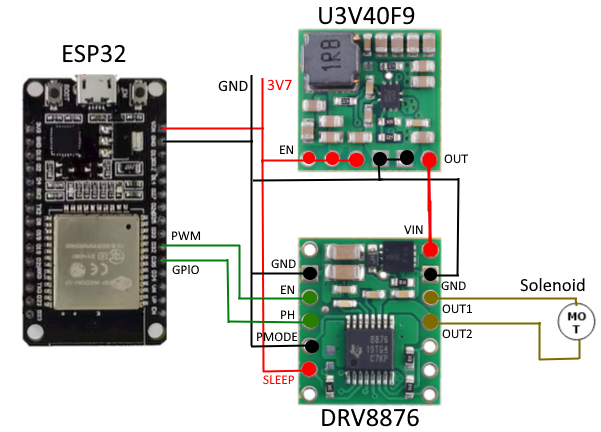
I’m trying to control a 9V Latch Solenoid with an ESP32 powered with a 3.7v battery.
I’m using a U3V40F9 connected to a DRV8876 and a PWM impulse for 100ms. It can close the valve but it cannot open it. It makes a coil sound when trying to open but it can’t. I tryied to change the time of the pulse, the values of the PWM and nothing works. It’s seems that there are not enough current to latch the solenoid.
The solenoid only needs a 500 mA pulse for 50ms to latch.
Can you post some pictures that show all of your physical connections? Can you make sure your battery is fully charged and monitor the voltage across the input and the output of the regulator while you are trying to control the solenoid?
If possible, I also suggest you try to confirm that the solenoid is working separately from the rest of your system. Do you have any other equipment you use for that, such as a bench-top adjustable supply that you could use to supply the solenoid with 9V directly?
The connections in your diagram seem okay, but could you also post some pictures of your actual setup, including close-ups of both sides of the boards, so I can check the soldering?
Looking at your setup with a scope should tell us more about what is actually going on. If you don’t have much experience using one, then this “How to Use an Oscilloscope” tutorial on SparkFun’s website might be a useful resource. As I suggested before, the first things I would suggest looking at are the voltages across the input and the output of the regulator. If that does not reveal any obvious problems, then you might also look at your control signals and the motor driver outputs, though make sure you are always attaching ground clips to ground. (Do not connect a ground clip to a motor driver output; that is a common mistake that could damage your probe.) Please take scope captures as you go so you can post them here.
I forget to tell you that I have a 1000uF/25V capacitor in the power supply. Without it the ESP32 reboot when the pulse to solenoid is done. I think this is a problem. The supply came from the ESP32.
The Osciloscope I have is an hold one from 2011. The USB port doesn’t work and connecting it to PC doesn’t work too. I can’t find drivers for Windows 10. So I take some pictures with my phone.
I haven’t read the link you sent me about how to use an osciloscope yet. I already use one like 30 years ago. I will read it later.
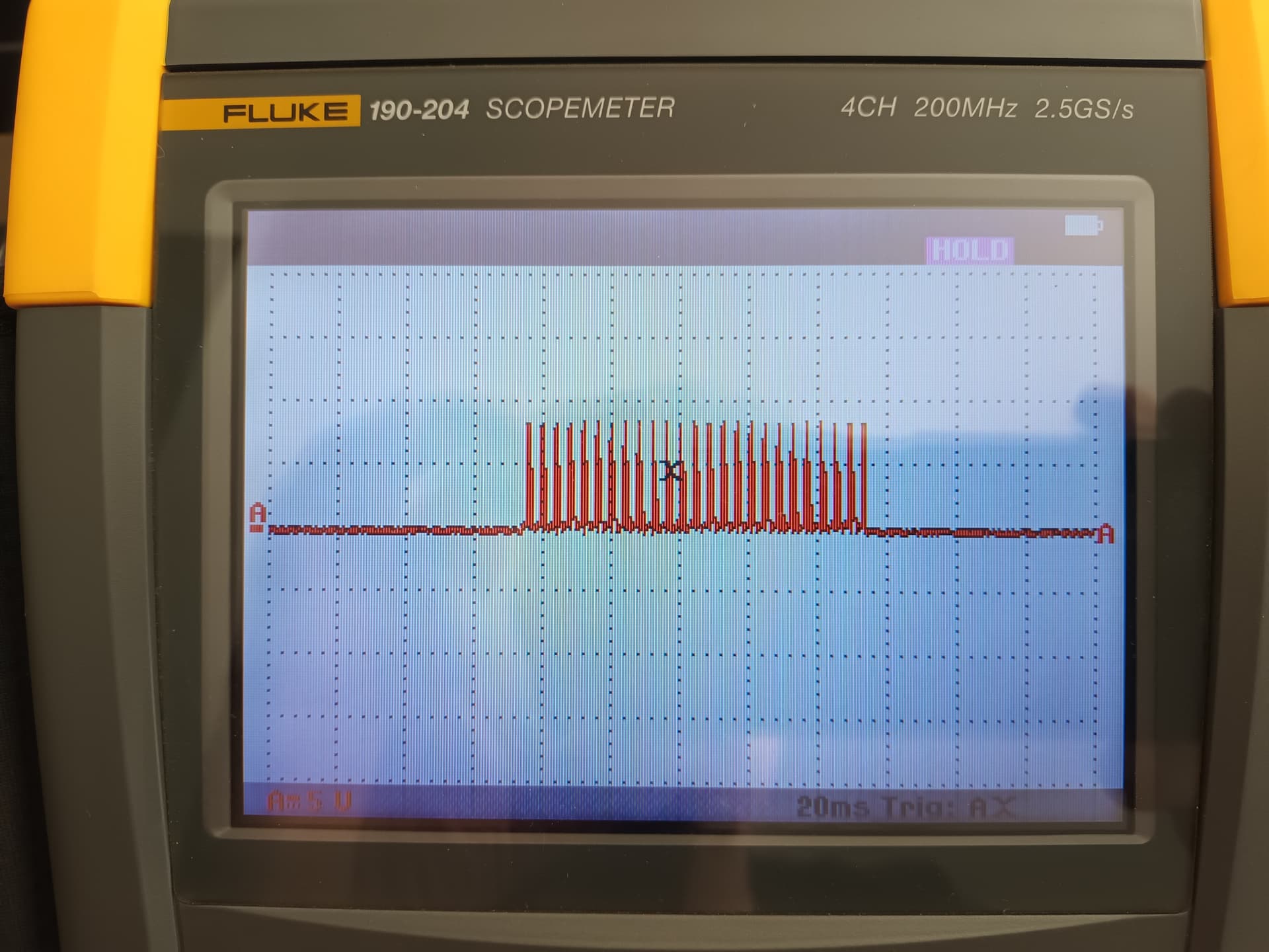
I take some measures with the osciloscope and 3 pictures.
The first one is from the power connection between the ESP32 and the breadboard (DRV8876 and U3V40F9). It seems there are a lot of noise an a drop in voltage.
The second one is from the Out1 from DRV8876.
The third one is from the Out2 from DRV8876.
What should I look to. I should measure the current but I don’t have a Clamp Meter. Any other way to measure current with osciloscope?
EDIT: I power the DRV887 and U3V40F9 with the 5v line from ESP32 instead of the 3v3 and remove the 1000uF capacitor and it started to work. This is supposed to work with a 3v7 Li-ion battery. I didn’t try with the battery yet. I had to put double wires in every VCC and GND too. Those little wires for breadboard didn’t help.
Next I will try with the 3v7 battery.
It sounds like you found at least one way to get your system working; I am glad to hear it!
In general, it seems like the scope captures from watching the power connection is the smoking gun here since that shows that the supply could not maintain the desired output voltage when the solenoid was drawing power. In general, I suspect the most important benchmarks for your setup are to make sure that supply and the 9V regulator’s output voltage stay close to constant during operation.
Yes, the relationship between voltage and current is dictated by Ohm’s law. Keep in mind that the most basic application of Ohm’s law (V = IR) probably does not tell the whole story here since it’s unlikely that the load from your solenoid is perfectly constant, but it seems like you have the right idea.