DRV8835 non-linear current draw vs PWM duty cycle

Hi,

I have a simple circuit with an Arduino, Pololu DRV8835, and a Pololu micrometal gearmotor.

I’m using the Phase/Enable mode, and varying the PWM duty cycle from 0-100%.

I notice the voltage (across the motor) increases linearly with PWM duty cycle and the motor spins proportionately faster (both as expected):

But I notice the current draw (from the batteries providing the motor power) is not linear, and in fact over twice as high at 50% than it is at 100%:

Is that expected?

I would have expected the current draw to be linear too. The website here suggests a linear relationship too.

I followed the wiring diagram on the DRV8835 website, and have separate 4xAA batteries powering motor. I added two capacitors (1000uf and 1uf) across the DRV8835 motor power inputs, VIn and Ground, and have my multimeter reading current flowing from batteries. (It didn’t give a good reading without the capacitors, I’m guessing since the current was pulsing).

For now, I’m using default PWM frequency on the Arduino Uno pin 9 which I believe is 490Hz from here.

The code I’m using for testing is below.

Btw, this happens in both directions. Also I’ve tried switching the motor and tried switching the DRV8835, and get consistent behaviour.

If this isn’t expected I can provide more details.

Regards,
Dan


const int modePin   = 12;
const int enablePin =  9; 
const int phasePin  = 10; 

void setup() {
  Serial.begin(9600);
  pinMode(modePin,   OUTPUT);
  pinMode(enablePin, OUTPUT);
  pinMode(phasePin,  OUTPUT);
  
  digitalWrite(modePin, 1);  // Set phase/enable mode
}

int phase = 0;

void loop() {

  digitalWrite(phasePin, phase);
  
  for (int enable = 0; enable <= 256; enable += 32) {
      analogWrite(enablePin, min(255, enable));
      Serial.print("phase=");      Serial.print(phase);
      Serial.print("\t enable=");  Serial.println(enable);
      delay(10000);
  }

  phase = 1 - phase;  // toggle phase
}

Hi again, (replying to my own post)

Does this relate to Phase/Enable mode braking during the low-time in the PWM cycle? Is the intuitive explanation that during the low-time the motor is braking so continually slowing up and speeding up, consuming more current than if it’s just staying at full speed?

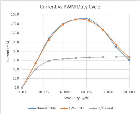
I tested also with In/In with Brake, and In/In with Coast. The In/In with Brake performs identically with the Phase/Enable, which makes sense.

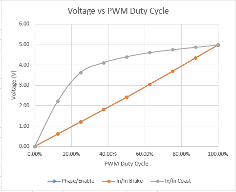
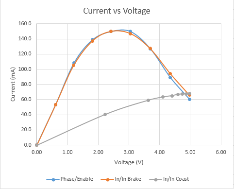
I found the results from In/In with Coast surprising too: the voltage increase and current increase with duty cycle wasn’t linear, but much steeper than linear. Why is that? However plotting Current vs Voltage was roughly linear. Charts below.

At 30%-70% PWM duty cycle, the current draw using Coast is approx half that with Brake. I notice that many of the motor drivers don’t even offer the Coast mode, though it seems much more efficient.

Would be interested in expert comments on this.

Also could I please confirm something from this forum topic:

since it seems that with Phase/Enable (or In/In with Brake) that the current involved will actually be considerably higher than at 6V, and considerably higher than even a steady 9V.

Thanks,
Dan

In this chart the Phase/Enable line is exactly under the In/In Brake

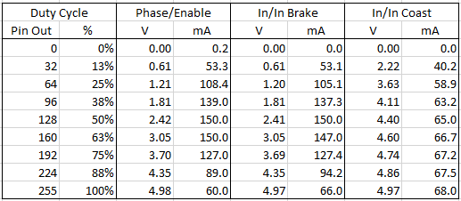
For anyone that’s interested, the measurements I got were:

The program I used for In/In timing is below.

Regards,
Dan


const int modePin = 12;
const int in1Pin  =  9; 
const int in2Pin  = 10; 

void setup() {
  Serial.begin(9600);
  pinMode(modePin, OUTPUT);
  pinMode(in1Pin,  OUTPUT);
  pinMode(in2Pin,  OUTPUT);
  
  digitalWrite(modePin, 0);  // Set in/in mode
}

int direction = 0;
int brake     = 0;  // 0==coast, 1==brake

void loop() {

  int pwmPin    = direction ? in1Pin : in2Pin;
  int otherPin  = direction ? in2Pin : in1Pin;
  digitalWrite(otherPin, brake);
  
  for (int speed = 0; speed <= 256; speed += 32) {
      int pwmValue = brake ? max(0, (255 - speed)) : min(255, speed);
      analogWrite(pwmPin, pwmValue);
      Serial.print("brake=");         Serial.print(brake);
      Serial.print("\t direction=");  Serial.print(direction);
      Serial.print("\t speed=");      Serial.print(speed);
      Serial.print("\t pwmValue=");   Serial.println(pwmValue);
      delay(10000);
  }

  direction = 1 - direction;  // toggle direction
  
  if (direction == 0)   // Toggle brake mode after going in both directions
    brake = 1 - brake;
}

Hi, Dan.

You’re on the right track with thinking about what happens during the “off” part of your duty cycle. The main reason you’re getting what you’re seeing is that your PWM frequency is so low that the current is changing a lot instead of averaging out nicely through a PWM cycle. If you increase the PWM frequency (around 20kHz is usually a nice target so that you don’t hear the whine), you should see a much nicer duty cycle to current relationship.

- Claire

Hi Claire,

Thanks very much for your answer.

Indeed that was the answer - as the PWM frequency increased the current draw became linear. As a beginner in this area, I didn’t appreciate that the PWM frequency had such effect on the dynamics of the motor.

At 20kHz I observed:

Regarding motor speed and torque, only the ‘Brake’ mode worked well - the ‘Coast’ mode just didn’t perform at all at higher frequencies. Now I understand why Brake is preferred! (I had guessed Coast would work better…)

I looked at the current draw across a range of frequencies for various PWM duty cycles. This chart shows for 25%, 50% and 75% duty cycle (with ‘Brake’ mode only):

It was interesting that the current dropped off slightly above 10kHz (below what would be exactly proportional based on duty cycle). Clearly not that important, but does this suggest 10kHz is slightly preferable to 20kHz for this motor? I can hardly hear any high pitch noise at this frequency, though perhaps it’s louder for others…

This has been interesting exercise as I learn about this topic. [Btw I wrote a little sketch that let me adjust the frequency and duty cycle with potentiometers and switch the brake/coast mode and direction with buttons as I experimented. I can post if any one is interested].

Thanks again,
Dan

Your measurements are all of the current to the board, not the current in the motor, right? Keep in mind that there are some losses in the driver proportional to the switching frequency, so those start becoming more prominent as the frequency goes up.

Terms like “brake” and “coast” can be misleading since, as you have seen, it depends on the time scale you are working on. At a long time scale, you can tell the clear difference between brake and coast modes by trying to spin a motor with the leads shorted or not. The idea with using the “brake” mode in PWM is that you use the inductance of the motor to keep the current going more smoothly. If your frequency is too low, though, as it was in your initial tests, there is enough time during those off parts of the duty cycle for the direction of the current to change and for the motor to actually get slowed down again; obviously, if you’re constantly trying to get it started and then slowing it down, it’s not going to be very efficient.

Hi, yes, my measurements are current to the board. So I guess current to the motor may be slightly less still under the higher frequencies.
Thanks,
Dan