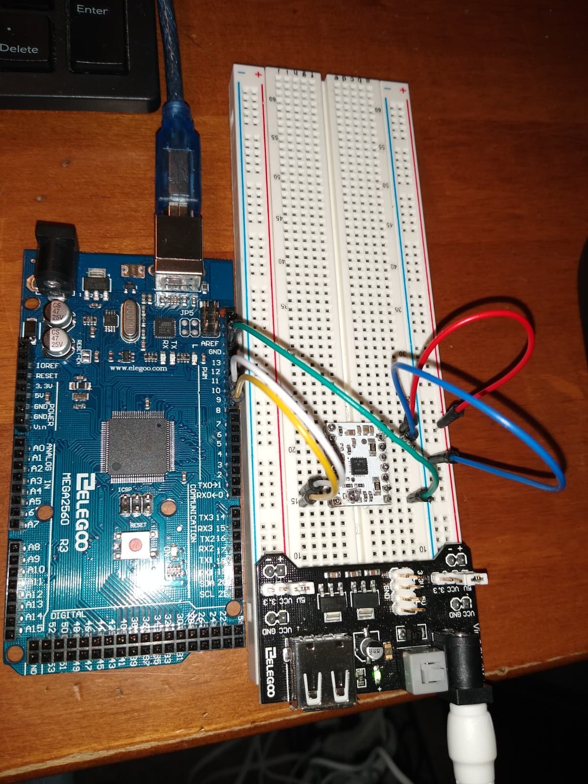
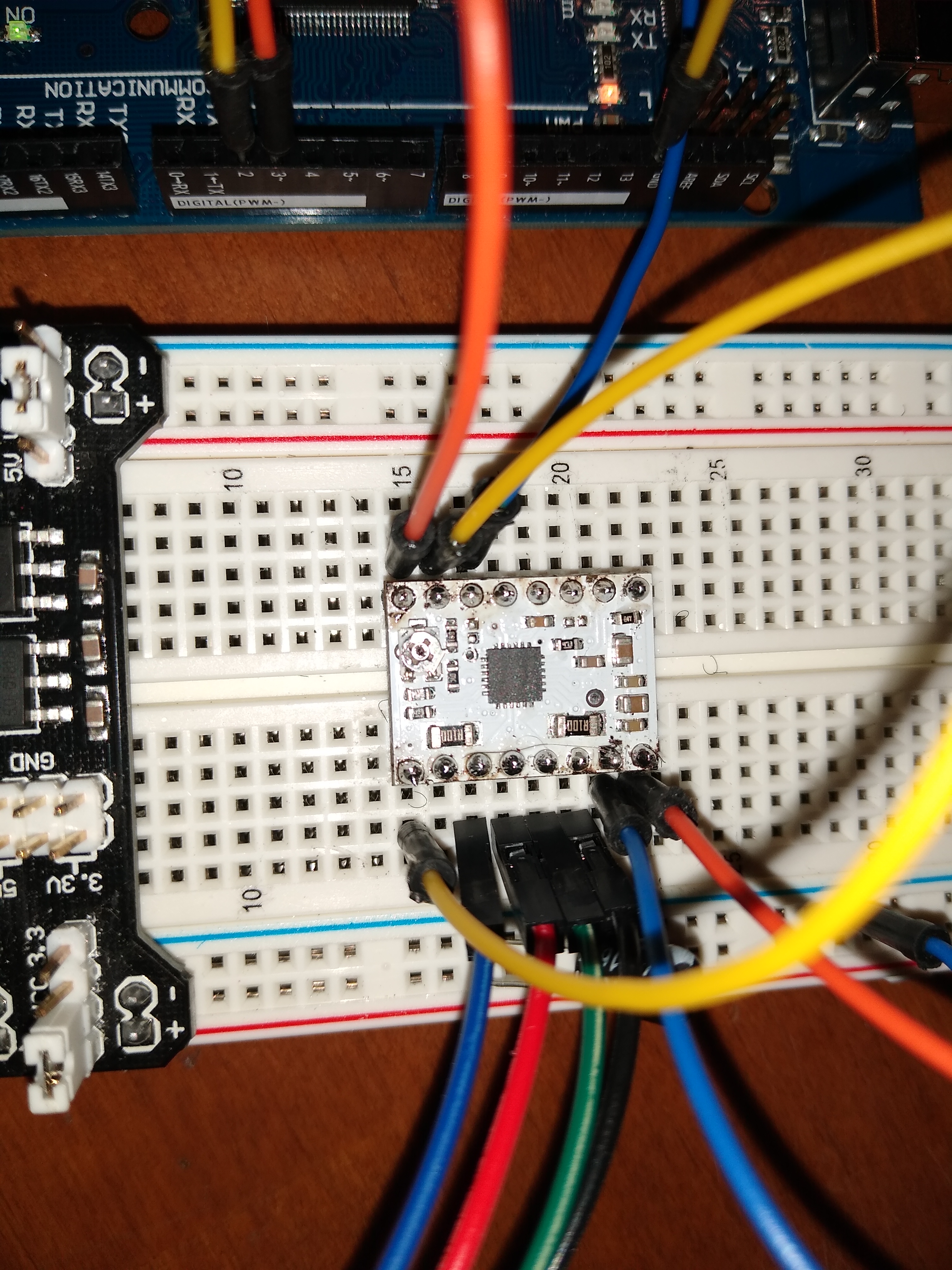
The system being built consists of a MEGA2560 controller powered via USB , an elego breadboard power supply and a DRV8834 driving a nema 17 bipolar stepper motor.
Voltage between carrier GND pin at the potentiometer end of the board and VMOT pin is 5.0 V.
Voltage between the carrier GND pin and small circle port is 0V
No current to the motor when I connect it.
The driver carrier is new.
Any suggestions would be appreciated. Thanks.
/*
 * Simple demo, should work with any driver board
 *
 * Connect STEP, DIR as indicated
 *
 * Copyright (C)2015-2017 Laurentiu Badea
 *
 * This file may be redistributed under the terms of the MIT license.
 * A copy of this license has been included with this distribution in the file LICENSE.
 */
#include <Arduino.h>
#include "BasicStepperDriver.h"
#include "DRV8834.h"

// Motor steps per revolution. Most steppers are 200 steps or 1.8 degrees/step
#define MOTOR_STEPS 200
#define RPM 120

// Since microstepping is set externally, make sure this matches the selected mode
// If it doesn't, the motor will move at a different RPM than chosen
// 1=full step, 2=half step etc.
#define MICROSTEPS 2

// All the wires needed for full functionality
#define DIR 8
#define STEP 9
//Uncomment line to use enable/disable functionality
//#define SLEEP 13

// 2-wire basic config, microstepping is hardwired on the driver
BasicStepperDriver stepper(MOTOR_STEPS, DIR, STEP);

//Uncomment line to use enable/disable functionality
//BasicStepperDriver stepper(MOTOR_STEPS, DIR, STEP, SLEEP);

void setup() {
    stepper.begin(RPM, MICROSTEPS);
    // if using enable/disable on ENABLE pin (active LOW) instead of SLEEP uncomment next line
    // stepper.setEnableActiveState(LOW);
}

void loop() {

    // energize coils - the motor will hold position
    // stepper.enable();

    /*
     * Moving motor one full revolution using the degree notation
     */
    stepper.rotate(360);

    /*
     * Moving motor to original position using steps
     */
    stepper.move(-MOTOR_STEPS*MICROSTEPS);

    // pause and allow the motor to be moved by hand
    // stepper.disable();

    delay(5000);
Hello.
It appears you have several solder balls, so those joints might not be fully wetted to the pads which is required to make good electrical connections. I recommend fixing that first. The Adafruit Guide to Excellent Soldering, specifically the “Common Soldering Problems” section might be a useful reference for that.
Once you think the soldering is okay you will need to add a connection to the nSLEEP pin. It needs to be driven high to enable the driver. If you continue having trouble with the driver after that, can you post some updated pictures of your board and connections?
- Patrick
Thanks, Patrick. I’ll do that.
Well, I redid the solder joints and tied nSLEEP to logic high. I set VREF to 500mV to match the 1A per coil specs for my NEMA 17 stepper.
The motor does not turn but locks in one position and cannot be turned by hand. It also sets up a high pitched whine. Here is my current current setup.
#include <Arduino.h>
#include "BasicStepperDriver.h"
#include "DRV8834.h"

#define MOTOR_STEPS 200
#define RPM 120

#define MICROSTEPS 3

#define DIR 8
#define STEP 9
BasicStepperDriver stepper(MOTOR_STEPS, DIR, STEP);

void setup() {
    stepper.begin(RPM, MICROSTEPS);
}
void loop() {
    stepper.rotate(360);
    stepper.move(-MOTOR_STEPS*MICROSTEPS);
    delay(5000);
Hello.
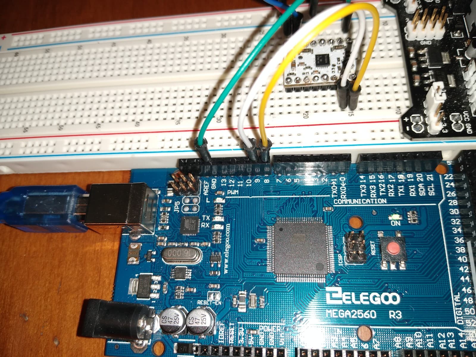
Your close-up picture of the board is attached in a way where it is stuck in a low resolution state and I cannot zoom into it, so I cannot see most of the solder joints that well. Could you try reposting that picture or posting a higher resolution one?
It sounds like your motor is at least getting powered now. When you run your code does it sound like your motor is skipping steps? The motor would be making a repetitive thumping sound. If the motor is not even trying to step, then that might suggest an issue with your code. We did not write the libraries you are using and I am not specifically familiar with them, so could you try something less abstracted, like the example program from this blog post?
- Patrick
I loaded up the script you suggested but I have the same results. Motor does not move and puts up a high pitched whine.
Some of your solder joints still do not look great. In particular, it seems like the GND pin in the bottom left corner of the board in your latest picture might not be fully wetted to the square pad.
Does it sound like the motor is trying to step, but it is skipping, or do you only hear the high pitched whine? Does the result change if you put the driver in full-step mode? You can do that by connecting the M0 pin to GND.
- Patrick
Well, OK. I touched up the soldering again and now the motor has stopped whining. However instead of stepping the motor once every every 500 ms as the program reads, it steps once every three seconds or so. Changing to full step mode produces one step per second in alternating directions…
#define STEP_PIN 2
#define DIR_PIN 3
bool dirHigh;
void setup()

{

dirHigh = true;

digitalWrite(DIR_PIN, HIGH);

digitalWrite(STEP_PIN, LOW);

pinMode(DIR_PIN, OUTPUT);

pinMode(STEP_PIN, OUTPUT);

}
void loop()

{

// Toggle the DIR pin to change direction.

if(dirHigh)

{

dirHigh = false;

digitalWrite(DIR_PIN, LOW);

Serial.print(“28”);

}

else

{

dirHigh = true;

digitalWrite(DIR_PIN, HIGH);

}
// Step the motor 50 times before changing direction again.

for(int i = 0; i < 50; i++)

{

// Trigger the motor to take one step.

digitalWrite(STEP_PIN, HIGH);

delay(250);

digitalWrite(STEP_PIN, LOW);

delay(250);

Serial.print(“h1”);

}

}
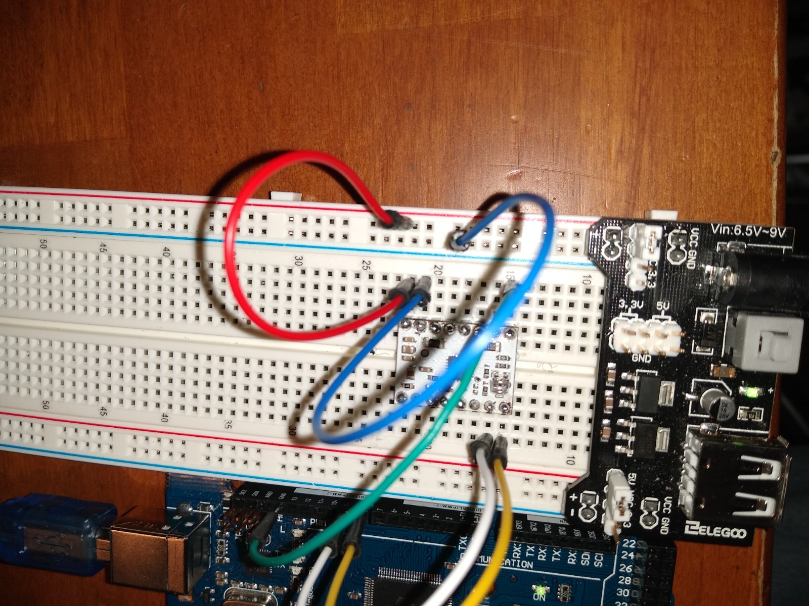
If all you did is try to fix the soldering again and the results changed like this, then it unfortunately seems like you are still having connection issues. Can you post updated pictures of your soldering from a few different angles? I suspect soldering remains the most likely culprit, but you might also try moving your driver to a different location on your breadboard just in case some of the rails there have been damaged. Breadboards are not designed to handle high currents, so if you have appropriate jumper wires you might even consider trying to test your driver by wiring to it directly instead of going through the breadboard.
Can you also try probing the STEP and DIR pins at the driver while your system is running to check that the control signals are behaving as expected? An oscilloscope would be the ideal tool for that if you have access to one, but the stepping is slow enough in your program that a multimeter should be sufficient as well.
- Patrick
Hello again! I probed the STEP and DIR outputs with an oscilloscope and the signals seem correct: nice square waves at 1/4 second intervals at STEP and alternating high and low at DIR at 10 second intervals or so. I tried probing motor output and get multiple peaks at a very high frequency. The motor whines, can not be turned by hand, and does not step.
I have done a good bit of resoldering and am wondering if I could have fried the driver by overheating a pin. Is that likely?
Just to clarify, are you able to get your motor to step at all now? In an earlier post you said you could get some stepping behavior, it was just not what we expected. If your motor is no longer stepping at all, then it is possible that resoldering the pins several times could have damaged it.
Do you have a different, more powerful supply that you can try for your motor supply? Also, if you have another driver board available, you might try it out to see if you get the same results.
- Patrick
There is no stepping at all. I do not have a more powerful supply at the moment, but I might try stringing up some 9v batteries in parallel and see what I get. I have an unused driver board that I can try as well. To follow up on the oscilloscope results, do you know in general what I should be seeing at the motor outputs?
What you observed on your oscilloscope sounds consistent with what we would expect from current limiting stepper motor drivers like the DRV8834.
I think it is worth trying out your unused board now as long as you can get the soldering right the first time. If you are not confident about that, then maybe consider finding something to practice a little more with first.
Alkaline 9V batteries are not appropriate for powering your stepper motor. They cannot supply enough current, and even having several in parallel will probably still not be sufficient. As far as batteries go, something like a LiPo or maybe a SLA battery would be more appropriate, but the ideal tool at this stage of testing would be an adjustable benchtop power supply. Do you know anyone who might have one that you could use, or is there perhaps a Makerspace or some other community resources near you where you could access one? Alternatively, a wall-wart style supply that is rated to handle at least a few amps would probably work. For reference, here is a link to our selection of wall power adapters.
- Patrick
Do you recommend that I purchase a 5V or 9V wall style supply?
Using a higher voltage along with active current limiting will allow the motor current to ramp up faster making it easier for your motor to operate without missing steps, so I would generally recommend higher voltage supplies for powering stepper motors. However, if you are sticking with the DRV8834, please keep in mind that its maximum operating voltage is 10.8V, so a 9V supply does not leave you with much headroom. That will make it especially important to minimize the likelihood of destructive noise or LC spikes by taking precautions like minimizing the length of your power leads and installing a large electrolytic capacitor across VMOT and ground close to the board.
- Patrick
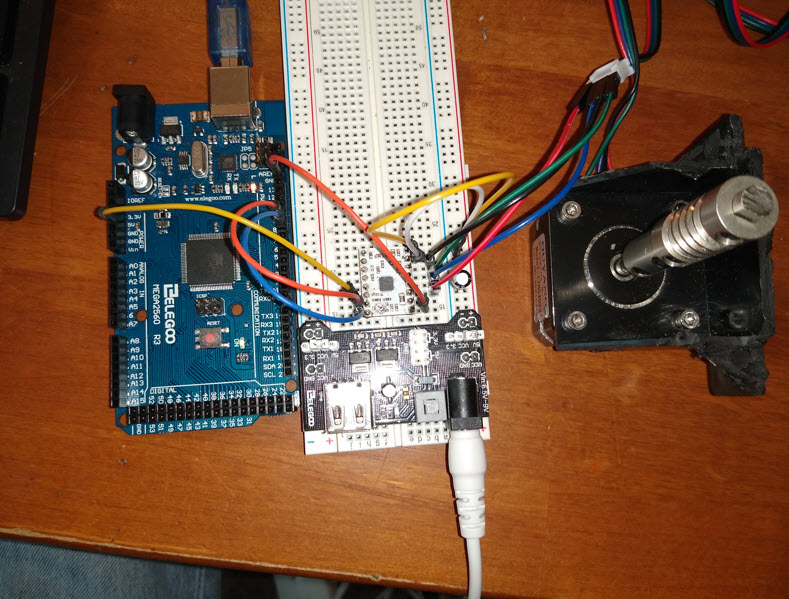
I am now using a 5V 3A power supply and a new presoldered DRV8834. HREF set to 500mv. I am running the basic stepper program you recommended. Nice oscilloscope output at STEP and DIR. I have checked, double checked, triple checked the wiring. The motor make steady rythmic noises as though it is trying to step, but does not rotate at all. The motor is locked in position , cannot be turned by hand, and is somewhat warm to the touch. Looking at the power connection socket on the motor I see that it has been stressed at some point and perhaps that is the problem. I think I’ll order another motor and see where that gets me.
If you suspect the motor connector is not making a good connection, then I agree that it would be worth trying a different stepper motor. You might also measure the resistance across each coil to see if it makes sense. Can you also post a datasheet or product page link for the stepper motor you are currently using?
- Patrick
Replaced the motor ,used a presoldered 8834 and upgraded the power supply, and… the motor stepped correctly. I swapped back to the original motor and 8834 that I had soldered and it continues to step nicely… If you don’t succeed at first… 
Thanks for all of your support.
Peter
ps: and now I have my own oscilloscope!
2 Likes
I am glad to hear you got it working now! Thanks for letting us know.
- Patrick