Just finished my first project using Pololu Jrk 12v12’s. It’s a drive by wire throttle controller for automotive use.
When I started this project I was deciding between building the entire circuit myself or using a motion controller to drive the throttle motors and providing them with my own positioning information. I chose the latter and after looking at several options I went with the Pololu Jrk 12v12. A great product IMO.
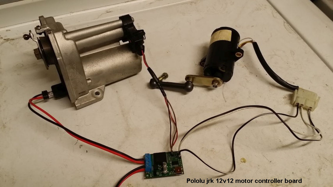
So what does a drive by wire (DBW) throttle do? It replaces the mechanical throttles in an engine with ones driven by an electric motor. The components are:
Accelerator pedal with sensors.
Throttle body with drive motor.
Throttle position sensors in the throttle body.
A controller to integrate everything.
Anyone remember the runaway Toyotas last year? One issue they had was with sticky gas pedals (these cars had DBW throttles). DBW control systems have a large number of safety systems in place. Since your throttle is under computer control, you’d want to make sure your control system is rock solid and stable.
There are many ways manufacturers do this. Pedal and throttles actually have a pair of position sensors. And these sensors have different voltage outputs and curves. The controller has to compare these curves and if they deviate then something is wrong with the pedal or throttle. In this case the throttles would be in ‘limp’ mode limiting engine power. Other things to look for are slow moving or ‘sticky’ throttles that don’t follow position commands quickly enough. Finally there’s calibration. The controller moves the throttles through a pattern from fully closed to open and measures the sensors. This is done when the vehicle powers up but before engine start. This way the controller can detect small changes over time (like spring pressure on the throttle) and make small adjustments so throttle ‘feel’ remains the same over the life of the car.
I used the Jrk’s to drive the motors while all the redundancy, safety checks and calibration are handled by my own circuit comprised of a pair of PIC’s. I build a PCB with connectors to allow the two Jrk’s to piggyback and plug on. If the Jrk’s prove reliable enough for long term use in an automobile then I’ll keep using them. If not, then I can make my own daughterboards while still keeping my original PCB.
Typing this on my iPhone while riding the train, will add more (and pics) later.
Wow! That sounds like quite a project, and I am happy to hear you like the Jrk motor controller. I hope you have some kind of backup plan for cutting power; are those some relays you have under your own PIC control?
Yes, those relays can dis-connect the throttle motors. It’s a last resort if for some reason giving a position command or resetting the Jrk fails to return the throttle to its desired position.
If I can’t determine for sure the throttles are closed (for example, if both throttle sensors stopped working at the same time - like from a damaged or severed cable) then I use the relays to cut power.
Electronic throttles have a spring loaded mechanical rest position (slightly opened) they will return to when power is cut, and this results in a fast engine idle. So you can still operate the vehicle to allow you to get off the road or park.
HI Nick,
Would it be a wild guess that you are trying to control the throttle on a BMW throttle.
I am using BMW throttle parts and feel this board can do the job of control. As regards the safty part of the project I think the after market ECU can do some cross checking of what we are getting from a safety stand point.
Using the Jrk 12v12 should mean there is no need to build any circuts,
.
Tony
I am late to this conversation - but am also interested in using a BMW Throttle Actuator to control mt Weber 8 Stack Carbs on a non-ecu 383 SBC. It is a racecar and I am looking to use the BMW actuator, a Throttle/Position Sensor and the Pololu 12v12 board. Are there any pictures of this? - these seem to be “gone” - and not on the Wayback either. Thanks - Jim
I did find this image - and that is what pointed me here. I note the Pololu 12v12 is a legacy device. What would be a reasonable replacement? This is exactly what I’m looking to build. Thanks - Jim
Brandon - Thanks for the update/details. I’ll check it out. This wiring looks pretty straightforward. Don’t think I’d need the USB port on the Jrk G2 18v19. I’m sure it is useful in some applications. Cheers - Jim